THE AUTOMATIC TRANSMISSION
Section
General description

Power flow diagram (Mechanical)
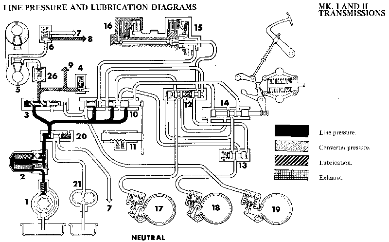
Line pressure and lubrication diagrams
Adjustments and checks
Governor control rod (kick-down) adjustment
Inhibitor switch adjustment
Selector lever cable and transverse rod adjustment
Oil pressure and stall speed checks

Auxiliary pump and governor
Differential assembly
Fault diagnosis
First gear free-wheel assembly (one-way clutch)
Forward clutch
Gear train
Lubrication reservoir (idler gear bearing)
Selector lever mechanism
Servo assembly
Top and reverse clutch
Transmission unit

Valve block
Removing and refitting
Dismantling and reassembling (units without the engagement and shuttle valves)
Dismantling and reassembling (units with inbuilt engagement and shuttle valves)

GENERAL DESCRIPTION

The automatic transmission incorporates a three-element fluid torque converter with a maximum torque conversion ratio of 2 : 1 coupled to a bevel gear train which provides four forward gears and reverse.

Engine power is transmitted from the crankshaft converter output gear through an idler gear to the input gear which drives the bevel reduction gears in the gear train assembly.

The final drive is transmitted from a drive gear to a conventional-type differential unit (similar to that fitted to a synchromesh transmission unit), which in turn transmits engine power through two flange-type coupling drive shafts employing constant velocity joints to the road wheels.

The complete gear train assembly, including the reduction gear and differential units, runs parallel to, and below, the crankshaft and is housed in the transmission casing which serves also as the engine sump.
The system is controlled by a selector lever within a gated quadrant marked with seven positions, and mounted centrally on the floor of the car. The reverse, neutral, and drive positions are for normal automatic driving, with the first, second, third, and fourth positions used for manual operation or over-ride as required. This allows the system to be used as a fully automatic four-speed transmission, from rest to maximum speed with the gears changing automatically according to throttle position and load. If a lower gear is required to obtain greater acceleration, an instant full throttle position, i.e. 'kick-down' on the accelerator, immediately produces the change.

Complete manual control of all four forward gears by use of the selector lever provides rapid changes. However, it is very important that downward changes are effected at the correct road speeds otherwise serious damage may result to the automatic transmission unit. The second, third, and top gears provide engine braking whether driving automatic or manual; in first gear a free-wheel condition exists when decelerating. Manual selection to third or second gear gives engine braking and also allows the driver to stay in a particular lower gear to suit road conditions or when descending steep hills.

The hydraulic system

Oil is drawn from the transmission casing through the main gauze strainer and pick-up pipe by the main oil pump which has a high potential output and serves both the engine lubrication and transmission systems with a common oil supply. The oil passes through drillings in the cylinder block and a pipe to the external full-flow filter and thence to the valve block.

The valve block assembly controls pressures to the transmission. Separate valves control the converter and engine pressures. The oil passes from the valve block through a long connecting pipe to the converter stator unit. Three short interconnecting pipes take the necessary line pressure to each of the servos which control brake band operation in manual and automatic selector positions.

The power flow through the bevel reduction gears is coupled to the final drive gear pinion by means of two multi-disc clutch assemblies operated hydraulically in manual and the automatic selector positions. In the event of tow-starting the engine, an auxiliary oil pump of low capacity is employed which is responsive to vehicle speed only; immediately the engine starts the main pump automatically takes over.

The governor system
The governor is driven by auxiliary pump gears and is of the spring-loaded mechanical type, with its bobweights mounted on short links. A rod linkage transfers the movement to the governor valve incorporated in the valve block chest.
A spring-loaded rod connected to the carburetter provides an over-ride device. The spring tends to be compressed by accelerator pedal operation, and transfers this load by levers to the governor. The effect is to delay travel of the governor, which in turn delays gear shifts more as the accelerator is depressed.

The torque converter
This is fitted onto a taper on the rear of the crankshaft. Basically it comprises three elements, i.e. an impeller, a turbine, and a stator, but it is only serviced as a unit.

There is a continuous supply of oil circulating through the unit; this assists in dissipating the heat generated, and the out-flow passes through a low-pressure valve which maintains a 30 lb./sq. in. (2.1 kg./cm2)pressure within the converter to improve efficiency.

The brake bands and servos
Three brake bands are used. One is for reverse and the others provide second and third speed reactions. The clamping load is applied by three hydraulic servos in a common casing.

The multi-disc clutches
For forward motion a single-piston multi-disc clutch carries the drive and is engaged at all times during forward motion of the car. This forward clutch unit is fitted on one side of the final drive pinion and on the other side is a top and reverse clutch assembly which has a tandem piston arrangement. This feature is necessary because the clutch is also engaged for reverse and since a greater torque capacity is required in this case both pistons are pressurized.

The valve block
Two types of valve block may be fitted, the later type is fitted to the Mk.II B type transmission units and these assemblies can be identified by the prefix to the serial number starting at the letter 'K'.
The later type valve block incorporates an engagement control device which comprises an additional control valve and two shuttle valves and these are located together with the various other valves in the valve chest and pipe chest sections of this unit.
The assembly is constructed of three basic units, i.e. the lid, valve chest, and pipe chest, with a separator plate fitted between the lid and the valve chest on the later assembly.
A linkage arrangement locates the selector valve and this in turn is controlled by the selector rod, externally connected by cable to the gear selector lever in the car. The function of the various valves is as follows:

THE SELECTOR VALVE directs oil from the main supply to either the governor valve for automatic gear-shifting or alternatively to the appropriate clutch or servo for manual selection.

THE REGULATOR VALVE controls the main line pressure, a secondary piston on the valve boosts this pressure when reverse is selected.

THE GOVERNOR VALVE movement is controlled by the mechanical governor and it directs the oil flow to the appropriate clutch or servo for automatic gear-shifts.

THE RELAY VALVES are used for shifts from second to third and third to top. They enable the clutch or servo required to be supplied either from the selector valve in ,manual' control or the governor valve in 'automatic'. In addition, pistons are fitted in front of the second and third relay valves to ensure that on up-shifts the engagement of the new ratio and release of the old occur simultaneously to prevent engine overspeeding between shifts. A relay valve is not required for the first gear as the torque reaction is controlled mechanically by a one-way clutch.

THE TOW START VALVE is only fitted to the early type valve block; it short-circuits the auxiliary pump under all normal driving conditions but supplies the required line pressure for tow starting. Immediately the engine starts the main pump automatically takes over. TOW STARTING IS NOT POSSIBLE when a transmission is fitted with a later type valve block which incorporates the engagement control valve.

THE ENGAGEMENT CONTROL VALVE has a primary function of eliminating harsh engagement when selecting 'D' or a forward gear from the rest position.

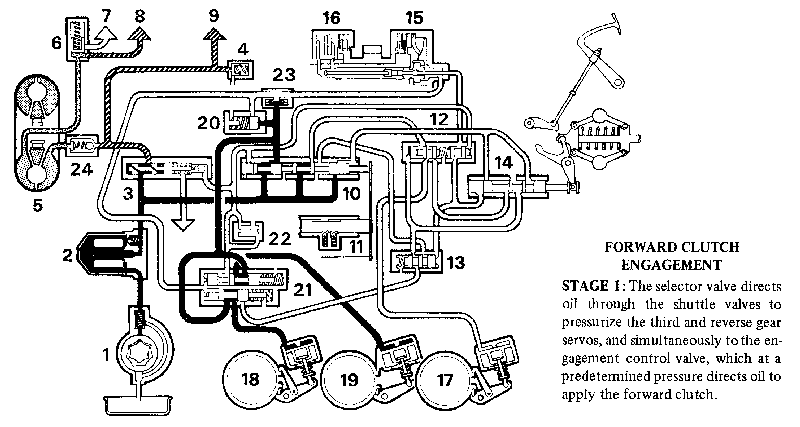
OPERATION OF ENGAGEMENT CONTROL VALVE When a forward gear is selected, the selector valve in the valve block directs oil to shuttle valves located in the back of the valve block. The oil passes through the shuttle valves and pressurizes the third and reverse gear servos, thus applying the brake bands and bringing the rotating components of the gear train gently to rest. The oil flows simultaneously to the engagement control valve which, at a predetermined pressure, directs oil to the forward clutch; and as there is relatively little movement between the driving and driven members the gear engagement is smooth.
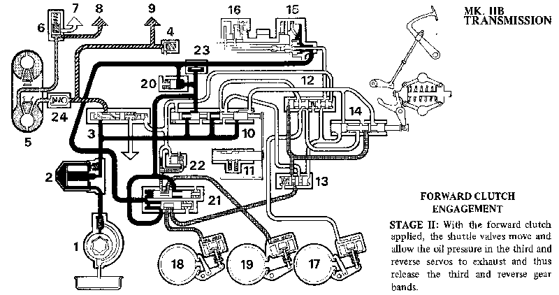
To complete the operating sequence, oil is also fed behind the shuttle valves which move and allow the oil pressure in the third and reverse servos to exhaust, thus releasing the third and reverse gear bands.

The low-pressure valve
This valve controls the pressure in the converter to 30 lb./sq. in. (2.1 kg./cm.2). When the engine is stopped the valve is seated, preventing the converter draining. This avoids difficulties in checking the combined engine/transmission oil level and prevents a noisy and inefficient converter when restarting the engine.

The auxiliary pump
This unit is used for tow-starting. It is of limited capacity and is responsive to road speed only.

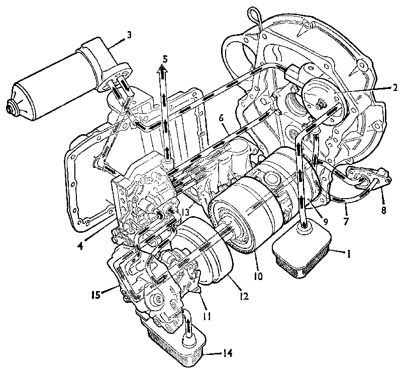
p04.gif
The components of the automatic transmission with the lubrication system and 'power flow' indicated by arrows to the various components

1. Main oil strainer.
2. Oil pump.
3. Oil filter assembly.
4. Valve block.
5. Engine oil feed.
6. Converter feed pipe.
7. Converter to low pressure valve feed.
8. Low pressure valve.
9. Gear train.
10. Top and reverse clutch.
11. Governor.
12. Forward clutch.
13. Servo unit.
14. Auxiliary pump oil strainer.
15. Auxiliary pump.

POWER FLOW DIAGRAMS (MECHANICAL)

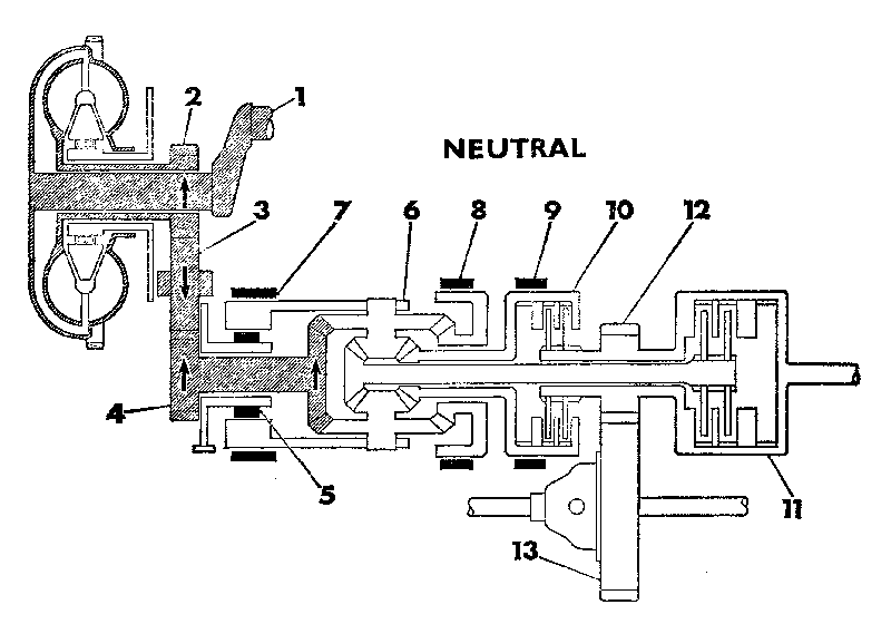
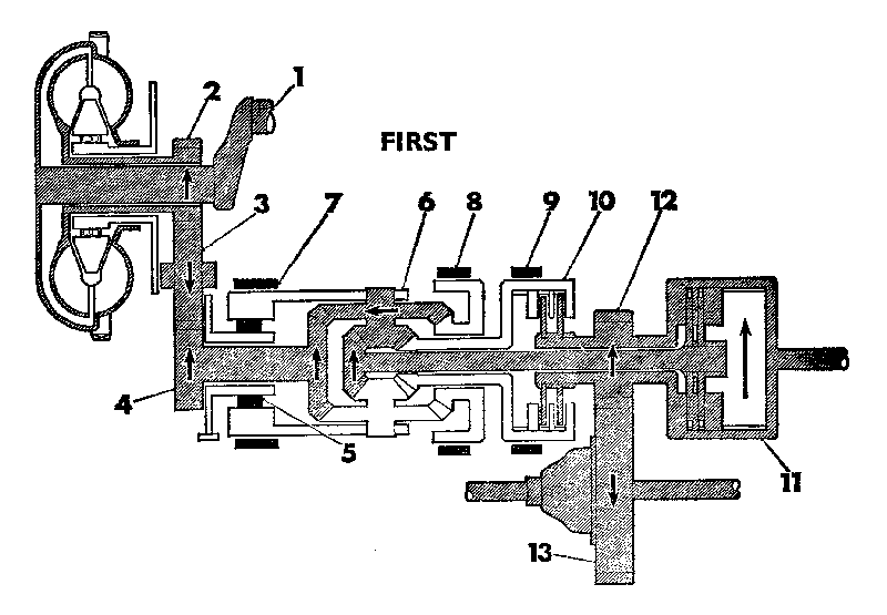
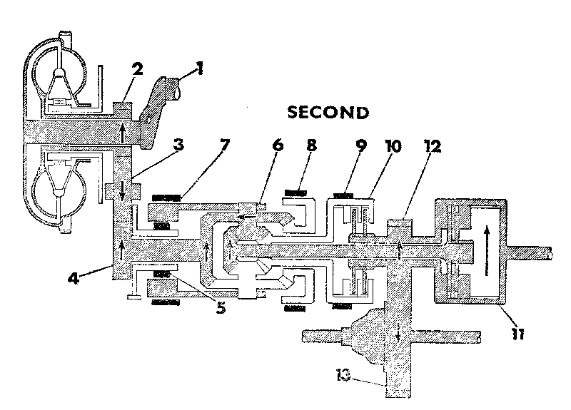
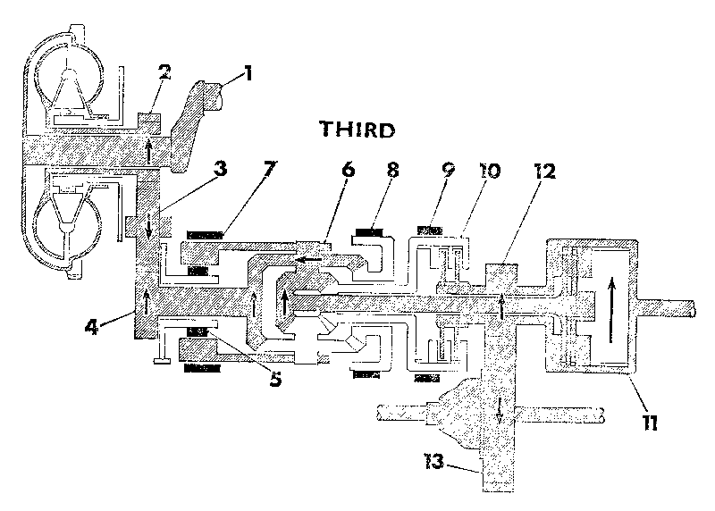
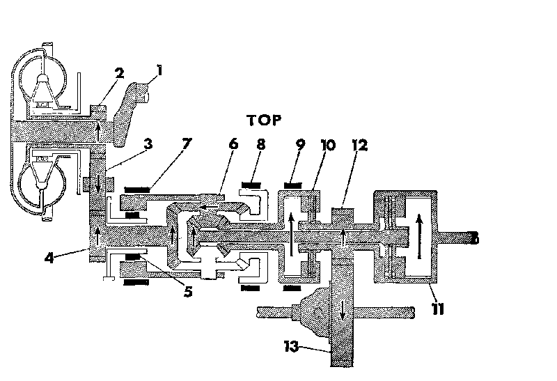
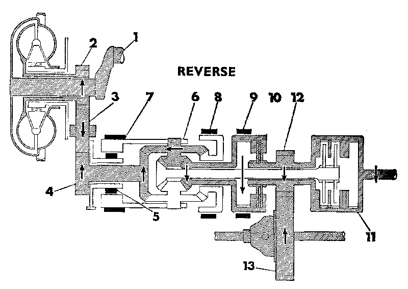
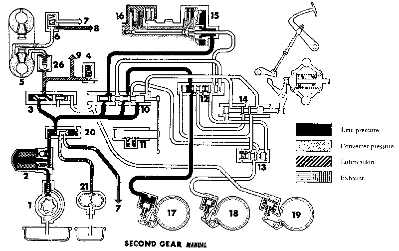
The power flow diagrams indicate how the various ratios are obtained. Four speeds and reverse are provided and these are brought into operation by engaging the appropriate friction members.
NEUTRAL

p05a.gif
KEY TO COMPONENTS

1. Crankshaft.
2. Converter output gear.
3. Idler gear.
4. Input gear.
5. One-way clutch.
6. Gear carrier.
7. Reverse band.
8. Third gear band,
9. Second gear band.
10. Top and reverse clutell
11. Forward clutch.
12. Final drive pinion.
13. Final drive gear.

NEUTRAL
When in neutral all the bands and clutches are disengaged, therefore there is no drive to the final drive pinion.

FIRST

p05b.gif
KEY TO COMPONENTS

1. Crankshaft.
2. Converter output gear.
3. Idler gear.
4. Input gear.
5. One-way clutch.
6. Gear carrier.
7. Reverse band.
8. Third gear band,
9. Second gear band.
10. Top and reverse clutell
11. Forward clutch.
12. Final drive pinion.
13. Final drive gear.

FIRST SPEED
In this ratio the forward clutch is applied and the one-way clutch is operative. The carrier is stationary, its reaction being controlled by the one-way clutch. The input bevel drives the planet wheels and the planet pinions drive the forward output pinion and shaft. Thus power is transferred through the planet assemblies to the mainshaft, forward clutch, and the output gear, providing a ratio of 2.69 : 1.

POWER FLOW DIAGRAMS (MECHANICAL)

SECOND SPEED
As for all forward gears the forward clutch remains engaged, and in addition the second speed brake band applied. This controls the reaction which is imposed on the reverse drive bevel when in this ratio. With the planet cluster orbiting around the reverse drive bevel power is transmitted from the input bevel through the planets to the mainshaft and provides a ratio of 1.845 : 1.

SECOND

p06a.gif
KEY TO COMPONENTS

1. Crankshaft.
2. Converter output gear.
3. Idler gear.
4. Input gear.
5. One-way clutch.
6. Gear carrier.
7. Reverse band.
8. Third gear band.
9. Second gear band.
10. Top and reverse clutch.
11. Forward clutch.
12. Final drive pinion.
13. Final drive gear.

THIRD

p06b.gif
KEY TO COMPONENTS

1. Crankshaft.
2. Converter output gear.
3. Idler gear.
4. Input gear.
5. One-way clutch.
6. Gear carrier.
7. Reverse band.
8. Third gear band.
9. Second gear band.
10. Top and reverse clutch.
11. Forward clutch.
12. Final drive pinion.
13. Final drive gear.

THIRD SPEED
For this ratio the third speed bevel wheel is held by its appropriate drum and brake band, and in this case the planet clusters orbit around this gear. Like second speed, power is transmitted from the input bevel through the planets to the mainshaft and in this case provides a ratio of 1.46 : 1..

POWER FLOW DIAGRAMS (MECHANICAL)

TOP SPEED
In addition to the forward clutch, the top and reverse clutch is engaged. This in effect locks up the bevel gears and the reduction gear assembly then rotates as one unit to provide direct drive.

TOP

p07a.gif
KEY TO COMPONENTS
1. Crankshaft.
2. Converter output gear.
3. Idler gear.
4. Input gear.
5. One-way clutch.
6. Gear carrier.
7. Reverse band.
8. Third gear band.
9. Second gear band.
10. Top and reverse clutch.
11. Forward clutch.
12. Final drive pinion.
13. Final drive gear.

REVERSE

p07b.gif
KEY TO COMPONENTS
1. Crankshaft.
2. Converter output gear.
3. Idler gear.
4. Input gear.
5. One-way clutch.
6. Gear carrier.
7. Reverse band.
8. Third gear band.
9. Second gear band.
10. Top and reverse clutch.
11. Forward clutch.
12. Final drive pinion.
13. Final drive gear.

REVERSE
In this ratio the carrier is held by the reverse band (the one-way clutch being inoperative because the reaction is in the opposite direction to first speed). In addition the top and reverse clutch is engaged. The input bevel wheel drives the planet wheel and the planet pinion drives the reverse drive gear. Thus power is transmitted through the planet assemblies to the top and reverse clutch and thence to the final drive pinion to provide a ratio of 2.69 : 1.

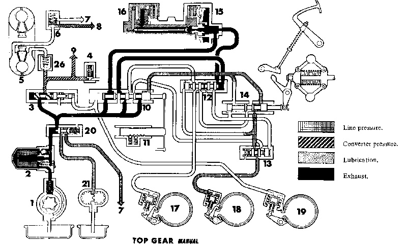
LINE PRESSURE AND LUBRICATION DIAGRAMS MK. I AND II TRANSMISSIONS

NEUTRAL
p08a.gif
KEY TO DIAGRAMS
1. Main oil pump.
2. Oil filter.
3. Regulator valve.
4. Engine lubrication relief valve.
5. Converter.
6. Low pressure valve.
7. To sump.
8. Gear train lubrication.
9. Engine lubrication.
10. Selector valve.
11. Selector valve detent.
12. Second and top gear valves.
13. Third gear valve.
14. Governor valve.
15. Forward clutch.
16. Top and reverse clutch.
17. Second gear brake band.
18. Third gear brake band.
19. Reverse gear brake band.
20. Tow start valve.
21. Auxiliary pump.
26. Restrictor valve (in converter pipe).

p08b.gif
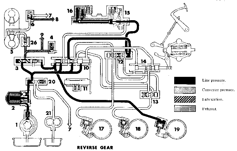
REVERSE GEAR
KEY TO DIAGRAMS
1. Main oil pump.
2. Oil filter.
3. Regulator valve.
4. Engine lubrication relief valve.
5. Converter.
6. Low pressure valve.
7. To sump.
8. Gear train lubrication.
9. Engine lubrication.
10. Selector valve.
11. Selector valve detent.
12. Second and top gear valves.
13. Third gear valve.
14. Governor valve.
15. Forward clutch.
16. Top and reverse clutch.
17. Second gear brake band.
18. Third gear brake band.
19. Reverse gear brake band.
20. Tow start valve.
21. Auxiliary pump.
26. Restrictor valve (in converter pipe).

LINE PRESSURE AND LUBRICATION DIAGRAMS MK. I AND II TRANSMISSIONS

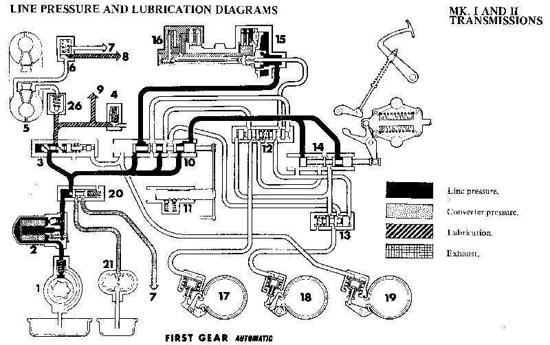
FIRST GEAR AUTOMATIC
p09a.gif
KEY TO DIAGRAMS
1. Main oil pump.
2. Oil filter.
3. Regulator valve.
4. Engine lubrication relief valve.
5. Converter.
6. Low pressure valve.
7. To sump.
8. Gear train lubrication.
9. Engine lubrication.
10. Selector valve.
11. Selector valve detent.
12. Second and top gear valves.
13. Third gear valve.
14. Governor valve.
15. Forward clutch.
16. Top and reverse clutch.
17. Second gear brake band.
18. Third gear brake band.
19. Reverse gear brake band.
20. Tow start valve.
21. Auxiliary pump.
26. Restrictor valve (in converter pipe).

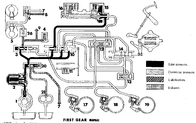
FIRST GEAR MANUAL
p09b.gif
KEY TO DIAGRAMS
1. Main oil pump.
2. Oil filter.
3. Regulator valve.
4. Engine lubrication relief valve.
5. Converter.
6. Low pressure valve.
7. To sump.
8. Gear train lubrication.
9. Engine lubrication.
10. Selector valve.
11. Selector valve detent.
12. Second and top gear valves.
13. Third gear valve.
14. Governor valve.
15. Forward clutch.
16. Top and reverse clutch.
17. Second gear brake band.
18. Third gear brake band.
19. Reverse gear brake band.
20. Tow start valve.
21. Auxiliary pump.
26. Restrictor valve (in converter pipe).

LINE PRESSURE AND LUBRICATION DIAGRAMS MK. I AND II TRANSMISSIONS

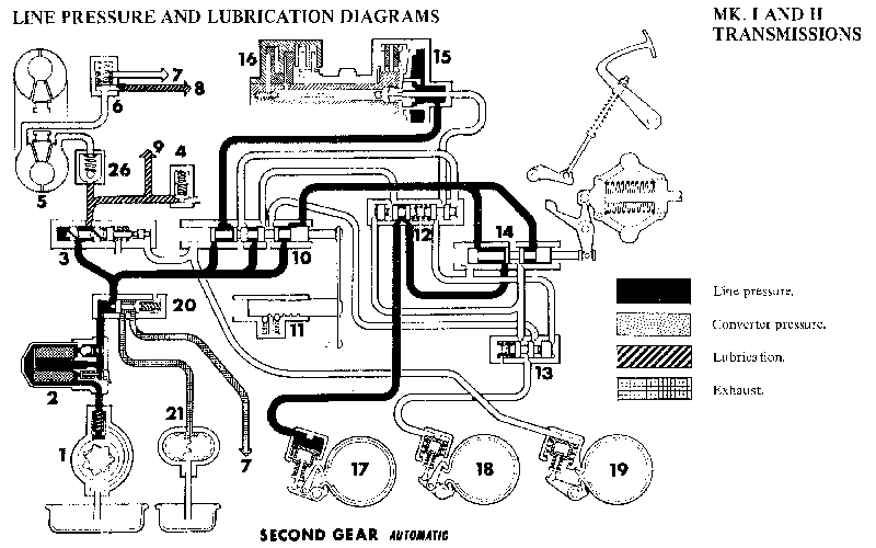
SECOND GEAR
p10a.gif
KEY TO DIAGRAMS
1. Main oil pump.
2. Oil filter.
3. Regulator valve.
4. Engine lubrication relief valve.
5. Converter.
6. Low pressure valve.
7. To sump.
8. Gear train lubrication.
9. Engine lubrication.
10. Selector valve.
11. Selector valve detent.
12. Second and top gear valves.
13. Third gear valve.
14. Governor valve.
15. Forward clutch.
16. Top and reverse clutch.
17. Second gear brake band.
18. Third gear brake band.
19. Reverse gear brake band.
20. Tow start valve.
21. Auxiliary pump.
26. Restrictor valve (in converter pipe).

SECOND GEAR
p10b.gif
KEY TO DIAGRAMS
1. Main oil pump.
2. Oil filter.
3. Regulator valve.
4. Engine lubrication relief valve.
5. Converter.
6. Low pressure valve.
7. To sump.
8. Gear train lubrication.
9. Engine lubrication.
10. Selector valve.
11. Selector valve detent.
12. Second and top gear valves.
13. Third gear valve.
14. Governor valve.
15. Forward clutch.
16. Top and reverse clutch.
17. Second gear brake band.
18. Third gear brake band.
19. Reverse gear brake band.
20. Tow start valve.
21. Auxiliary pump.
26. Restrictor valve (in converter pipe).

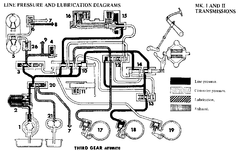
LINE PRESSURE AND LUBRICATION DIAGRAMS MK. I AND II TRANSMISSIONS

THIRD GEAR AUTOMATIC
p11a.gif
KEY TO DIAGRAMS
1. Main oil pump.
2. Oil filter.
3. Regulator valve.
4. Engine lubrication relief valve.
5. Converter.
6. Low pressure valve.
7. To sump.
8. Gear train lubrication.
9. Engine lubrication.
10. Selector valve.
11. Selector valve detent.
12. Second and top gear valves.
13. Third gear valve.
14. Governor valve.
15. Forward clutch.
16. Top and reverse clutch.
17. Second gear brake band.
18. Third gear brake band.
19. Reverse gear brake band.
20. Tow start valve.
21. Auxiliary pump.
26. Restrictor valve (in converter pipe).

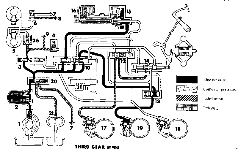
THIRD GEAR MANUAL
p11b.gif
KEY TO DIAGRAMS
1. Main oil pump.
2. Oil filter.
3. Regulator valve.
4. Engine lubrication relief valve.
5. Converter.
6. Low pressure valve.
7. To sump.
8. Gear train lubrication.
9. Engine lubrication.
10. Selector valve.
11. Selector valve detent.
12. Second and top gear valves.
13. Third gear valve.
14. Governor valve.
15. Forward clutch.
16. Top and reverse clutch.
17. Second gear brake band.
18. Third gear brake band.
19. Reverse gear brake band.
20. Tow start valve.
21. Auxiliary pump.
26. Restrictor valve (in converter pipe).

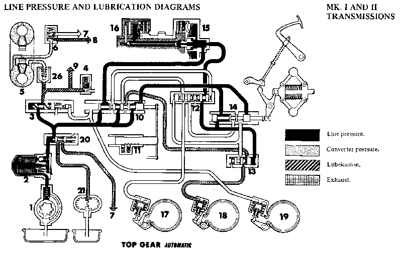
LINE PRESSURE AND LUBRICATION DIAGRAMS MK. I AND II TRANSMISSIONS

TOP GEAR
p12a.gif
KEY TO DIAGRAMS
1. Main oil pump.
2. Oil filter.
3. Regulator valve.
4. Engine lubrication relief valve.
5. Converter.
6. Low pressure valve.
7. To sump.
8. Gear train lubrication.
9. Engine lubrication.
10. Selector valve.
11. Selector valve detent.
12. Second and top gear valves.
13. Third gear valve.
14. Governor valve.
15. Forward clutch.
16. Top and reverse clutch.
17. Second gear brake band.
18. Third gear brake band.
19. Reverse gear brake band.
20. Tow start valve.
21. Auxiliary pump.
26. Restrictor valve (in converter pipe).

TOP GEAR MANUAL
p12b.gif
KEY TO DIAGRAMS
1. Main oil pump.
2. Oil filter.
3. Regulator valve.
4. Engine lubrication relief valve.
5. Converter.
6. Low pressure valve.
7. To sump.
8. Gear train lubrication.
9. Engine lubrication.
10. Selector valve.
11. Selector valve detent.
12. Second and top gear valves.
13. Third gear valve.
14. Governor valve.
15. Forward clutch.
16. Top and reverse clutch.
17. Second gear brake band.
18. Third gear brake band.
19. Reverse gear brake band.
20. Tow start valve.
21. Auxiliary pump.
26. Restrictor valve (in converter pipe).

LINE PRESSURE AND LUBRICATION DIAGRAMS MK. IIB TRANSMISSIONS

p13a.gif
2 FORWARD CLUTCH ENGAGEMENT
STAGE 1: The selector valve directs oil through the shuttle valves to pressurize the third and reverse gear servos, and simultaneously to the engagement control valve, which at a predefined pressure directs oil to apply the forward clutch.

KEY TO DIAGRAMS
1. Main oil pump.
2. Oil filter.
3. Regulator valve.
4. Engine lubrication relief valve.
5. Converter.
6. Low pressure valve.
7. To sump.
8. Gear train lubrication.
9. Engine lubrication.
10. Selector valve.
11. Selector valve detent.
12. See ond and top gear valves.
13. Third gear valve.
14. Governor valve.
15. Forward clutch.
16. Top and reverse clutch.
17. Second gear brake band.
18. Third gear brake band.
19. Reverse gear brake band.
20. Engagement control pressure valve (Mk. II B only).
21. Engagement control shuttle valves (Mk. II B only).
22. One-way dump valve (Mk. II B only).
23. One-way flap valve (Mk. II B only).
24. Restrictor valve (in converter pipe).

MK. II B TRANSMISSION

FORWARD CLUTCH ENGAGEMENT
STAGE ll: With the forward clutch applied, the shuttle valves move and allow the oil pressure in the third and reverse servos to exhaust and thus release the third and reverse gear bands.

p13b.gif
KEY TO DIAGRAMS
1. Main oil pump.
2. Oil filter.
3. Regulator valve.
4. Engine lubrication relief valve.
5. Converter.
6. Low pressure valve.
7. To sump.
8. Gear train lubrication.
9. Engine lubrication.
10. Selector valve.
11. Selector valve detent.
12. See ond and top gear valves.
13. Third gear valve.
14. Governor valve.
15. Forward clutch.
16. Top and reverse clutch.
17. Second gear brake band.
18. Third gear brake band.
19. Reverse gear brake band.
20. Engagement control pressure valve (Mk. II B only).
21. Engagement control shuttle valves (Mk. II B only).
22. One-way dump valve (Mk. II B only).
23. One-way flap valve (Mk. II B only).
24. Restrictor valve (in converter pipe).

FAULT DIAGNOSIS CHART
FAULTSRECTIFICATION SEQUENCE
Torque converter
Excessive creep or engine stalls when selecting gears2
Poor acceleration and difficulty in starting from rest on hills5
Severe overheating and reduced maximum speed in all gears6
Rattle from converter on engagement of gears and frequency increasing with engine speed, particularly, when under load6
Rattle or vibration from converter area in neutral and all gears11
Rattle or buzz in 'N' up to approximately 1250 r.p.m. Noise disappears on engagement of any gear48, 49, 50
Squeal from converter area in neutral and all gears12, 13
Gear selection and change speeds
Gear selections faulty3, 21
Kick-down change speeds incorrect7, 2
Change speeds incorrect on light throttle driving, possibly no drive in '1' or '4' of automatic 'D' range22, 23
Erratic change speeds in automatic 'D' range24, 25
'Tie-up' in 4 automatic 'D' range and/or transmission slip in automatic 1 and 43, 22, 23, 4
Clutch slip or 'flare up' on 3 to 4 change in automatic and manual ranges3, 22, 1, 4, 9, 28, 35, 36, 37, 42, 45
Vehicle moves off in 4 when any of the forward gears are selected and 'ties up' in reverse41, 42
No automatic gear changes, transmission slip in all forward gears43
Transmission slip/loss of drive
Complete loss of drive in all gear positions (transmission oil pressure normal), vehicle attempts to drive in 3 and 431, 32
Transmission slip in all gear positions1, 4, 9, 27, 28, 29, 30
Slip or no drive in reverse 'R'3, 1, 4, 9, 28, 8, 35, 36, 37
Slip or no drive in all forward gears1, 4, 33, 34
No drive in manual or automatic 138
Drive in 1 but 'tie-up' in 2, 3 and 4 manual or automatic38
Transmission slip in manual and automatic 2 or premature wear of second gear band3, 22, 28, 8, 39, 40
Transmission slip in 33, 8, 28, 39, 40
Slip or 'tie-up' on intermediate gear changes3, 4, 7, 23, 54
Drag in 4 and 'R' reverse, other gears function normally42
Pressures
Excessive transmission pressures when starting from cold, with possible oil leakage from oil filter bowl seal28, 44
Low engine oil pressure1, 4
Noise
Continual whine consistent with road speed but not in top gear51, 52
Continual whine consistent with engine speed except when car is stationary53
Noise or vibration with road speed in all gear positions26, 55
Oil leaks
Oil leaks fror converter area11, 14, 10, 15, 16, 17, 18, 19, 20
Oil leak from filter bowl seal, see 'Pressures'44, 28

DIAGNOSIS RECTIFICATION CHART

SEQ.RECTIFICATIONSECTIONSEQ.RECTIFICATIONSECTION
1Check oil level.Aa. 132.Check the bevel gear train planetary pinions.Fa. 1 2
2.Thoroughly check engine tune, idle and fast idle speeds, choke operation. also that the throttle opens fully.Da.233.Check fit of forward clutch feed pipe, the condition of all sealing rings (clutch feed) and ensure that correct cast iron sealing rings are fitted to forward clutch/auxiliary pump drive shaft.Fa.6, Fa. 11
3.Check selector lever cable and transverse rod adjustment.Fa.234.Check condition of clutch plates and piston in forward clutch. Check and rectify clutch plate end-float.Fa. 11
4.Carry out oil pressure check.Fa.535.Check feed pipes and sealing rings to top and reverse clutch and reverse band servo.Fa.7
5.Carry out stall test.Fa.536.Remove the top/reverse clutch from the gear train and check that the bush in the reverse output shaft has not turned and shut off the oil feed to the top/reverse clutch.Fa.12
6.Carry out road test.Fa. 137.Check top and reverse clutch piston ring gaps and fit of rings in the piston grooves; check condition of clutch plates.Fa. 13
7.Check governor control rod (kick-down) adjustment.Fa.438.Check if free wheel support dowel bolt is loose or sheared; replace if necessary.Fa.6
8.Check band adjustment.Fa.639.Examine servo feed pipes, seals, and servo piston seal.Fa. 11
9.Check location of sealing rings and/or joint washer under oil filter head.Aa.240.Examine 2nd gear band and replace if excessively heat darkened or worn. Replace top/reverse clutch if damaged by worn band.Fa.6, Fa. 13
10.Check tightness of converter drain plugs.Aa.341.Replace forward clutch.Fa. 11
11.Check if converter retaining bolt or the six hub bolts are loose,Aa.442.Check that the gear train thrust washers are correctly positioned, and that the top/reverse clutch circlip is correctly located.Fa.12, Fa. 13
12.Check converter housing bush for seizure or if loose in housing.Aa.443.Check the forward clutch auxiliary pump drive shaft for breakage; also check pump gears, replace forward clutch and auxiliary pump housing assemblies, if damaged.Fa.10, Fa.11
13.Check converter does not foul converter housing, or housing loose and fouling converter.Aa.444.Check torque tightness of filter bowl retaining bolt.'General Data'
14.Check low pressure valve for flange distortion or core plug leakage.Aa.445.Incorrect re-assembly of gear train; check and replace any damaged clutch plates and refit gear train correctly.Fa. 12
15.Check converter housing oil seal for damage or incorrect location.Aa.1546.Check that clutch plates are correctly engaged on hub.Fa. 13
16.Check for oil leakage from converter housing oil pump cover.Aa.447.Check condition of auxiliary pump gear thrust washer.Fa.10
17.Examine idler gear closed end bearing for leakage.Aa.448.Remove valve chest and check that correct regulator valve is fitted.Fa.8
18.Check for oil leakage from the converter hub bolt., (6).Aa.449.Check torque tightness of camshaft sprocket retaining nut.'General Data'
19.Check converter easing seam weld for oil leakage.Aa.450.Fit replacement oil pump assembly.Aa. 8
20.Check converter housing for porosity.Aa.451.Check the bevel input gear preload.Aa. 3
21.Check for correct assembly of the valve block, i.e. that the selector valve is engaged with the selector fork of the pipe chest.Fa. 752.Check the shim adjustment of the top/reverse clutch-assembly to gear train.Fa.12
22.Check setting and alignment of the valve block governor valve with the governor lever (on pipe chest).Fa. 753.Check the helical input and idler gear adjustment.Aa. 3
23.Check that correct governor/auxiliary pump assembly is fitted in relationship with valve block (two types of each unit (have been used).Fa.754.Check that the interconnecting feed pipe with the restricted bore is connected between the valve block and reverse serve.Fa.7
24.Check that the governor and governor valve operate freely; and for correct location of the valve block-governor link with the governor unit,Fa.755.Check condition of final drive gears and for correct pinion bearing preload.Fa 16, Fa.6
25.Check that the governor carrier shaft circlip is correctly positioned.Fa.10
26,Check the auxiliary pump gears and the alignment of the pump housing with the end cover.Fa.10
27.Remove front cover and check '0' rings on cover to valve block connection.Fa.6
28.Remove and clean valve chest.Fa.8 or 9
29.Check main oil pump; joint washer, retaining screws are tight, drive coupling, examine delivery pipe connections (pump to transmission case).Aa.8, Aa.9
30.Check oil pump pick-up pipe and oil strainer seals.Aa.4
31.Check converter feed pipe for blockage by blowing through with compressed air from the valve block end.I Aa.4, Fa.7

CHANGE SPEED CHART
SELECTOR POSITIONTHROTTLE POSITIONGEAR SHIFTM.P.H.Km.P.H.
'D'Light1-210-1416-22
2-315-1924-30
3-420-2432-39
'D'Kick-down1-225-3340-53
2-337-4560-72
3-449-5778-91
'D'Kick-down4-347-3976-64
3-239-3162-50
2-126-1841-29
'D'Closed (roll out)4-320-1632-26
3-214-1022-16
2-18-412-6

Section Fa. 1
FAULT DIAGNOSIS

It is important to carry out a thorough road test of the vehicle to establish the exact fault symptoms and to confirm which component(s) of the transmission are faulty or require adjustment. The mechanical power flow diagrams indicate the components in use for each gear. Always check the engine/transmission oil level and top up if necessary before commencing a road test. It may also be advisable to carry out the other preliminary checks detailed below.

Preliminary checks and tests

a. Check oil level (Section Aa.1).
b. Check engine idling speed (Section Da. 1).
c. Carry out oil pressure check (Section Fa.5).
d. Carry out stall test (Section Fa.5).

Road test procedure

GEAR SELECTION
1 . Check operation of gear selector in all seven positions as given below:
'N'. Check that there is key start in this position only, and not in the drive positions.
'1'. Confirm that there is drive and NO engine braking.
'2', '3', '4'. Confirm that there is drive WITH engine braking.
'D'. See 'CHANGE SPEEDS'.
'R'. Confirm that there is drive WITH engine braking.

CHANGE SPEEDS
2. Check the 'kick-down' up-change speeds in 'D' position, refer to the 'CHANGE SPEED CHART'.

Section Fa.2

SELECTOR LEVER CABLE AND TRANSVERSE ROD ADJUSTMENT

Checking

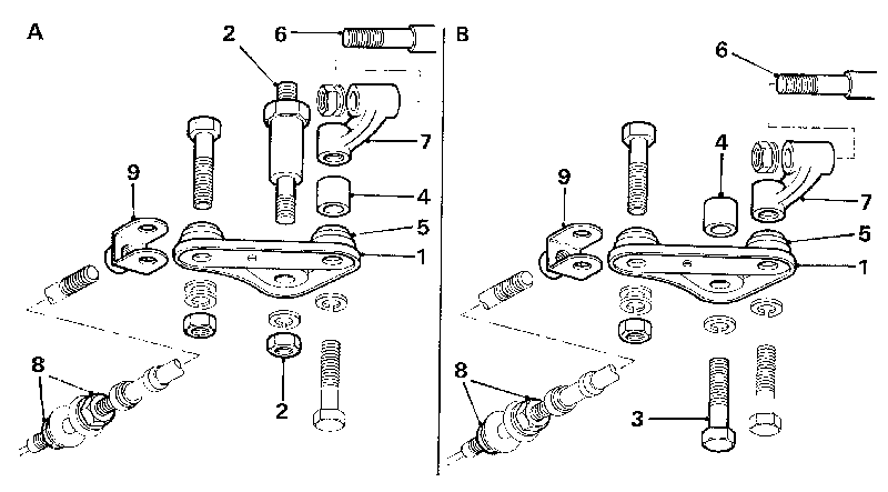
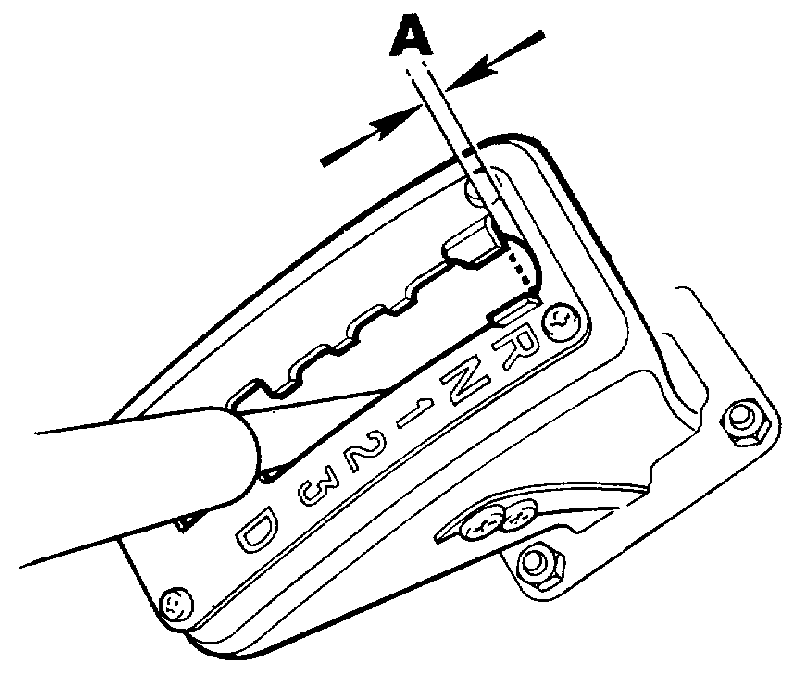
1. Ensure that the hand brake is applied and start the engine. Move the selector lever to the 'R' position and check that reverse is engaged. Slowly move the lever back towards the 'N' position, checking that the gear is disengaged just before or as soon as the lever drops in the 'N' position on the quadrant. Repeat this procedure in the first gear '1' position. If adjustment is necessary, proceed as detailed below and refer to Fig. Fa. 1.
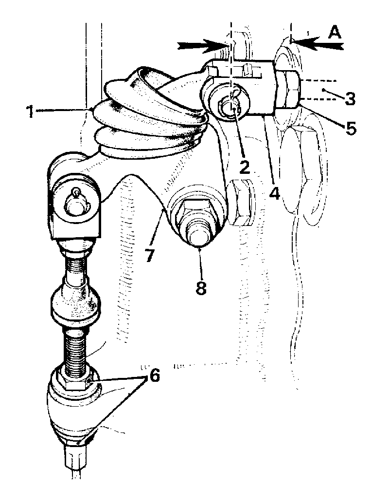
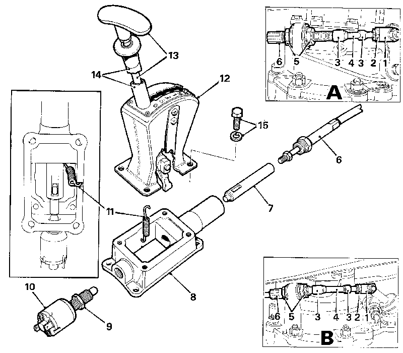
fa01.gif
Fig. Fa. 1
Both versions of the pressed-type minimum backlash bell-crank lever assembly, showing 'A' the first exposed type and 'B' the second enclosed type

1. Pressed bell-crank lever arm.
2. Bell-crank lever pivot pin and securing nut.
3. Bell-crank lever pivot bolt.
4. Collar.
5. Spherical joint.
6. Transverse rod.
7. Transverse rod bracket (fixed).
8. Cable adjusting nuts.

Adjusting

SELECTOR LEVER TRANSVERSE ROD (1 st TYPE)

2. Pull back the rubber boot and remove the clevis pin. Ensure that the transverse selector rod is screwed in tightly and pushed fully into the transmission case.

WARNING.- Never start the engine with the transverse selector rod disconnected.

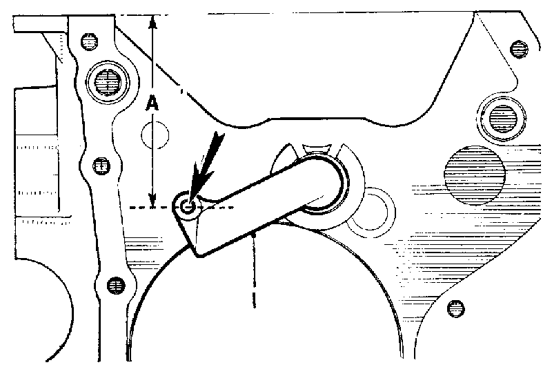
3. Swivel the bell-crank lever arm clear of the transverse selector rod yoke and refit the clevis pin. Check the measurement 'A' as shown in Fig. Fa.2 and, if necessary, adjust the yoke as described in item 4.
fa02.gif
Fig. Fa.2
The gear-change cable and transverse rod adjustment
(Forged-type bell-crank)
A = 25/32 in. (20 mm.) with transverse rod fully in

1. Rubber boot.
2. Clevis pin.
3. Transverse rod (adjustable).
4. Transverse rod yoke.
5. Yoke locknut.
6. Cable adjusting nuts.
7. Forged bell-crank lever arm.
8. Bell-crank lever pivot and securing nut.

4. Slacken the locknut and turn the yoke until the correct measurement is obtained. Re-tighten the locknut, ensuring that the yoke is set square to the bell-crank.

SELECTOR LEVER TRANSVERSE ROD (2nd TYPE)

The transverse rod is not adjustable and is fitted on units having the later-type minimum backlash bell-crank lever assembly (see Fig. Fa.1).

Selector lever cable

5. a. Transmissions with seven selector positions.
Select 'N' in the transmission unit by pulling the transverse rod fully out and then pushing it back in ONE detent.
b. Transmissions with six selector positions.
Proceed as above except that the transverse rod must be pushed back in TWO detents.
6. a. EARLY MODELS. Engage 'N' with the selector lever; adjust the selector cable until the hole in the cable fork aligns with the bell-crank lever and the clevis pin can easily be inserted (see Fig. Fa.2).
b. LATER MODELS. On units fitted with the minimum backlash bell-crank lever, the adjustment procedure is as detailed above except that the cable fork must align with the bore of the spherical joint in the bell-crank lever until the bolt can easily be inserted (see Fig. Fa.1).
NOTE: Ensure that the yoke end on the selector cable is secured square to the bell-crank lever before reconnecting.

7. Carry out the checking procedure in item 1; slight readjustment may be necessary so that the amount of movement to engage or disengage gears is equalized in both directions.
8. Tighten all adjustment/locking nuts and ensure that the clevis pins (when fitted) are secured. Pack the rubber boots (when fitted) with Duckhams Larnmol Grease, refit the boots and the bell-crank lever guard.
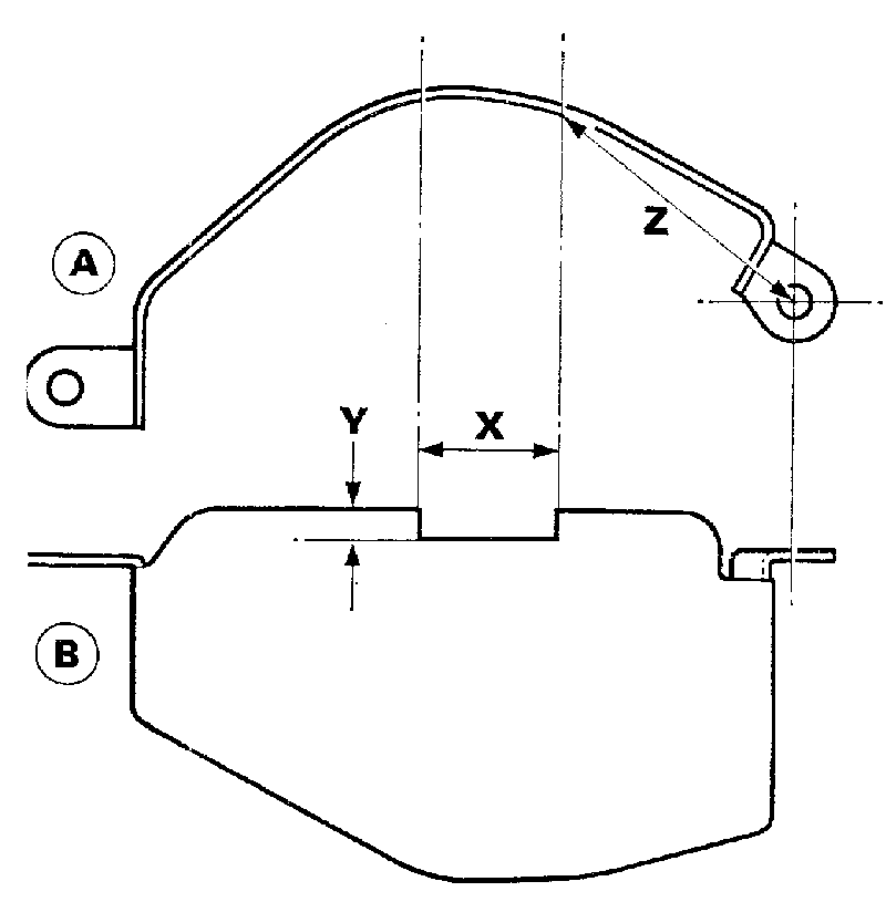
NOTE: The bell-crank lever guard fitted to units having the minimum backlash bell-crank is reshaped, but die earlier-type guard can be modified (see Fig. Fa.3) to use with the later-type bell-crank.
9. Carry out a road test checking the operation in each selector position.

Section Fa.3

INHIBITOR SWITCH ADJUSTMENT

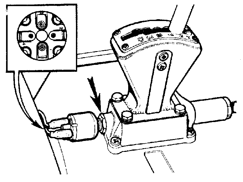
The switch is located on the rear of the gear selector housing (Fig. Fa.4) and must be adjusted to ensure that the engine can only be started when the selector lever is in the 'N' position on the quadrant.

The earlier-type switches have four terminals, two of which are connected through the ignition/starter circuit; later-type switches have two terminals only.

fa03.gif
Fig. Fa.3
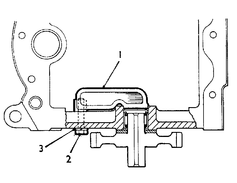
Reset the original bell-crank lever guard for use with the pressed bell-crank by bending it to the revised shape (view 'A') and adding the cut-out (view 'B') X=1 3/8 in (35 mm.) Y= 3/8 in. (9.5 mm.) Z=2 5/8 in. (67 mm.)

fa04.gif
Fig. Fa.4
The later type selector lever housing and two terminal type inhibitor switch. 'Inset' shows the earlier switch with four connections

ELECTRICAL CONNECTIONS
Ignition/starter circuit: Connect to 2 and 4 (wiring connections are interchangeable).
Reverse light (when fitted): Connect to 1 and 3.
Check the selector lever cable and transverse rod adjustment before adjusting the inhibitor switch.

Checking adjustment
1. Verify that the starter operates only when the selector lever is in the 'N' position, and also that the reversing light (when fitted) operates only when 'R' is selected.

Adjusting
2. Select 'N' and disconnect the electrical connections from the switch.
3. Slacken the locknut (arrowed, see Fig. Fa.4), and unscrew the switch almost out of the housing.
4. Connect a test lamp or meter across the switch terminals 2 and 4. Screw the switch into the housing until the circuit is made, and mark the switch body. Continue screwing in the switch and note the number of turns required until the circuit breaks. Remove the test equipment and unscrew the switch from the housing half the number of turns counted.
5. Tighten the locknut and refit the electrical leads to the appropriate terminals.
NOTE: - If the switch cannot be adjusted to operate correctly it must be renewed.

Section Fa.4

GOVERNOR CONTROL ROD (KICK-DOWN) ADJUSTMENT

Checking
1. Run the engine to its normal working temperature.
2. Check with a tachometer that the carburetter is adjusted to give an engine idling speed of 650 r.p.m.
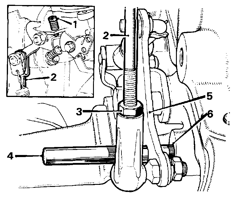
3. Disconnect the governor control rod at the carburetter, insert a 1/4 in. (6.4 mm.) diameter rod through the hole in the intermediate bell-crank lever and locate the hole in the transmission case (Fig. Fa.5).
4. Check if the control rod can now be re-connected to the carburetter with its fulcrum pin an easy sliding fit through the forked end and with the carburetter linkage.
Adjust if necessary, as detailed below.

Adjusting

5. Slacken the control rod locknut, disconnect the forked end at the carburetter linkage and turn the rod until the correct length is obtained. Connect up at the carburetter end, tighten the locknut and remove the checking rod (see Fig. Fa.5).
6. Road-test the car and check that automatic change speeds corresponds to those given in the 'CHANGE SPEED CHART' in Section Fa. 1.

If full throttle change speeds are LOW, disconnect the forked end of the rod, slacken the locknut and SHORTEN the rod; conversely, if full throttle change speeds are HIGH, turn the rod anticlockwise to LENGTHEN it slightly.

Road-test to ensure correct change speeds can now be obtained.

Section Fa 5

OIL PRESSURE AND STALL SPEED CHECKS

In suspected cases of slip or poor acceleration a converter stall speed check should be carried out as detailed below. If there is slip in all gears a low oil pressure is indicated which should be confirmed by a pressure check.

Oil pressure check
1. Check and top up the oil level (see Section Aa. 1).
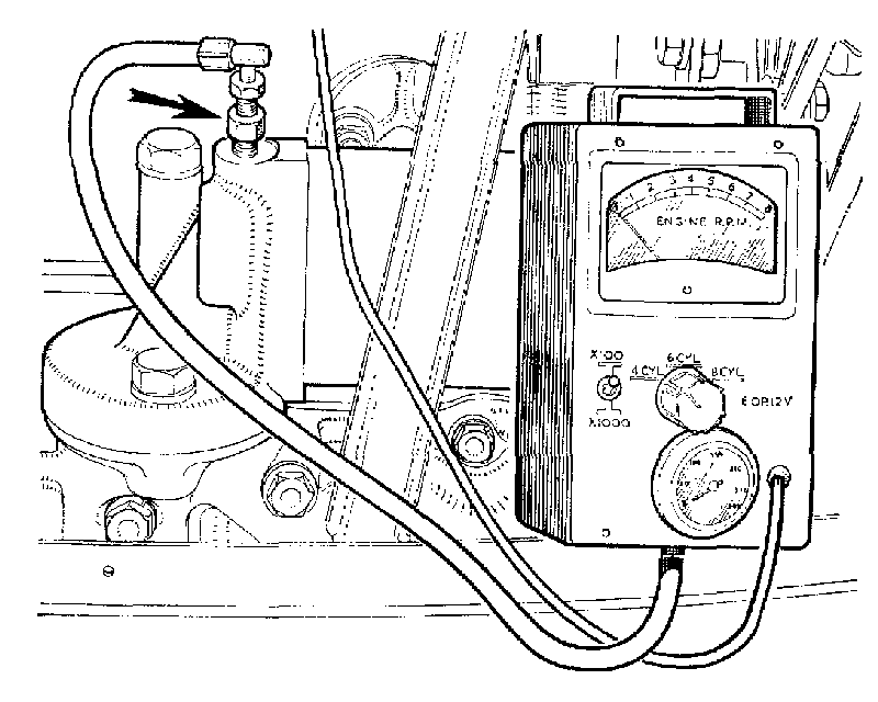
2. Remove the pressure point plug on the engine oil filter, fit Service tool adaptor 18G 677 C, and connect Service tool 18G 677 Z (see Fig. Fa.6) or use pressure gauge (Service tool 18G 502 A with pipe and adaptor 18G 502 K).
3. Start and run the engine until the oil temperature is 80' C - (176' F.) (check with a thermometer inserted into the dipstick hole). Re-start and run the engine at 1000 r.p.m. and check the following approximate pressures:

fa05.gif
Fig. Fa.5
The governor control rod adjustment
1. Throttle adjustment screw.
2. Governor control rod.
3. Locknut.
4. 1/4 in. (6.4 mm) diameter rod.
5. Intermediate bell-crank lever.
6. Transmission case hole.

a. In all gear positions except 'R' a pressure of between 75 and 85 lb./sq. in. (5.3 and 6 kg./cm.,) should register on the gauge.
b. In 'R' the pressure should be between 115 and 125 lb./sq. in. (8 and 8.8 kg./cm.).
NOTE. - Should the approximate pressures given above not be obtainable, see Section Fa.1, 'FAULT DIAGNOSIS'.
4. Remove the pressure test equipment and refit the plug.

fa06.gif
Fig. Fa.6
Checking the presures and the stall speed with Service tool 18G 677 Z and adaptor 18G 677 C (arrowed)

Stall speed check
5. Start and run the engine until it reaches its normal working temperature and check the oil level.
6. Connect a suitable tachometer or that of Service tool 18G 677 or 18G 677 Z (see Fig. Fa.6).
Service tool electrical connections:
18G 677 - Green to ignition coil CB.
Red to battery positive.
Black to battery negative.
18G 677 Z - Red to ignition coil CB.
Black to earth connection.
7. Apply the hand and foot brakes, select any gear position except 'N' or '1', apply maximum throttle for not more than 10 seconds and note the tachometer reading. Compare the figure obtained with the 'Stall speed' chart.

Stall speed chart
8. Disconnect the tachometer.
MODELR.P.M.ConditionRectification
848 c.c.1,300-1,400SatisfactoryNil
998 c.c.1,400-1,500SatisfactoryNil
Under 1,000Stator free wheel slipChange torque converter
Over 1,500Transmission slipsCheck transmission unit (see Road Test note)
848 c.c. and 998 c.e.Under 1,300Engine down for powerCheck engine

Section Fa.6

TRANSMISSION UNIT

Dismantling
1. Remove the engine and transmission from the car see Section Aa.3.
2a. Remove the transmission from the engine as detailed in Section Aa.4 only if fitting a replacement engine, transmission case, or if it is necessary to remove the main oil strainer pick-up pipe and seals.
2b. Remove the converter and converter housing as detailed in Section Aa.4, items 1 to 11 and 13.
3. Unscrew and withdraw the transverse rod and remove the front cover (the connection is pressed into the later-type cover).
4. Remove the governor control assembly from the transmission case and fit Service tool 18G 1097 (see Fig. Fa,19).
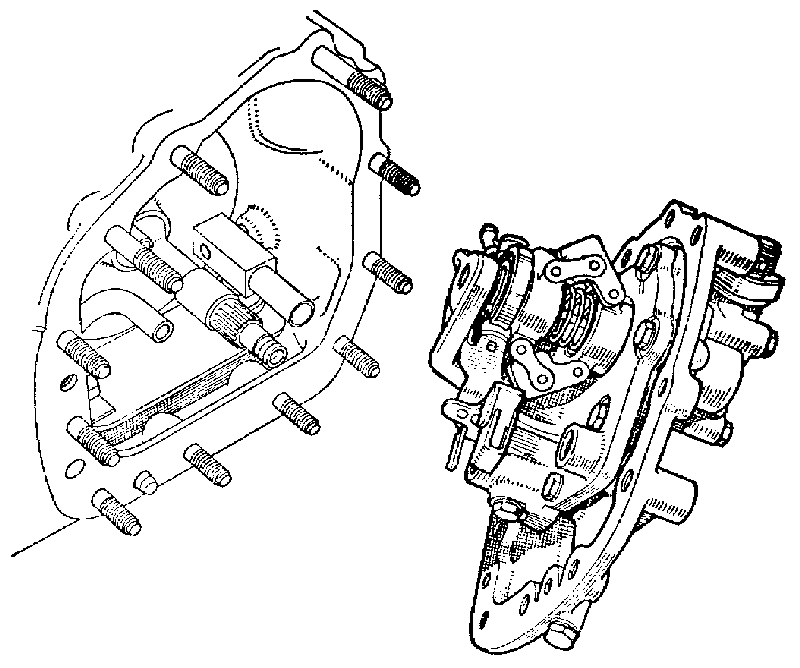
5. Remove the securing nuts and pull the auxiliary pump and governor assembly from the transmission case.
NOTE. - For auxiliary pump and governor dismantling and reassembling see Section Fa. 10.

fa07.gif
Fig. Fa.7
Removing the auxiliary pump and governor assembly

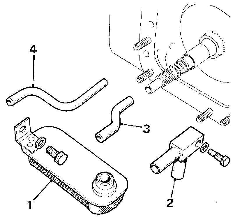
6. Remove the dowel bolt and pull out the auxiliary pump filter outlet pipe.
7. Pull out the auxiliary pump outlet and the forward clutch apply pipes.
8. Remove the set screw and lift out the auxiliary pump filter.
9. Remove Service tool 18G 1097 and withdraw the forward clutch from the easing.
NOTE. - For forward clutch dismantling and reassembling see Section Fa. 11.

fa08.gif
Fig. Fa.8
Removing the auxiliary oil pump strainer 1 and pipe 2, with 3 the outlet pipe, and 4 the forward clutch apply pipe

fa11.gif
Fig. Fa.11
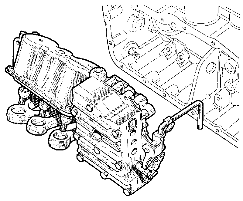
Removing the valve block and servo unit as an assembly

fa09.gif
Fig. Fa.9
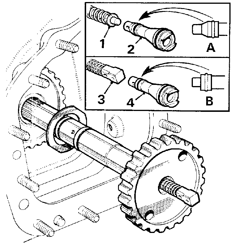
the forward output shaft and the reverse shut-off valve
Inset 'A'-1. Reverse shut-off valve I
2. Shut-off valve piston - early type
Inset 'B'-3. Reverse shut-off valve
4. Shut off valve piston - later type

10. Withdraw the forward output shaft and remove the reverse shut-off valve, which should be identified for reassembly. The Mk. II transmission is fitted with a shut-off valve having a squared bronze thrust pad (see Fig, Fa.9) and a modified valve piston having a square cut shoulder. These can only be interchanged as a pair and the fastest type should be fitted when rebuilding the transmission.
11. Insert the dummy output shaft Service tool 18G 1093 or 18G 1093 A.
12. Slacken off the servo band adjusters.

fa10.gif
Fig. Fa.10
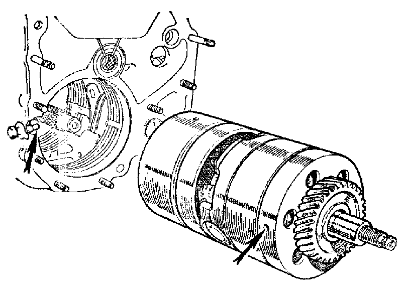
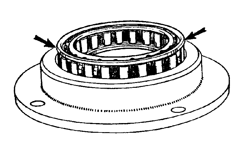
Removing the gear train assembly. The arrows indicate the dowel bolt and its location in the free-wheel support

13. Remove the dowel bolt (Fig. Fa.10) and remove the gear train which includes the top and reverse clutch with its Torrington needle thrust bearing and steel washer, and the first gear free-wheel assembly.
NOTE. - For gear train dismantling and reassembling see Section Fa. 12.
14. Remove the engine oil feed pipe as shown in Fig. Aa.9. On later transmissions unscrew the adaptor and withdraw the valve block connecting pipe through the adaptor hole.

fa12.gif
Fig. Fa. 12
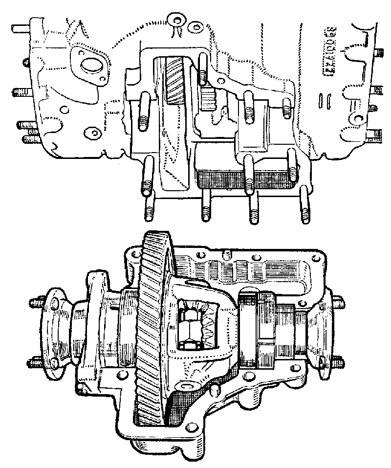
Removing the differential assembly

fa15.gif
Fig. Fa. 15
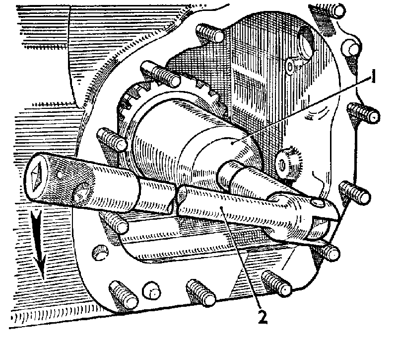
Removing the forward clutch hub nut
1. Service tool 18G 1096.
2. Socket handle.

fa13.gif
Fig. Fa.13
The main oil strainer, pick-up pipe and seals

15. Remove the valve block and servo unit securing bolts. Depress the tops of the bands and unhook them from the servos and lift out the valve block and servo unit as an assembly (Fig. Fa. 11).
NOTE. - For valve block dismantling and reassembling see Section Fa.8, 9. For servo unit dismantling and reassembling see Section Fa. 14.
16. Remove the bands from the transmission case.
17. Remove the governor control assembly from the transmission case.
18. Knock back the lock washers and remove the nuts from the differential housing and the differential end cover set screws. Remove the differential and housing assembly.
NOTE. - For differential dismantling and reassembling see Section Fa. 16.
19. Remove the main oil feed pipe and strainer (see item. 2a).

fa16.gif
Fi,. Fa.16
1. Forward clutch splines.
2. Selective thrust washer.
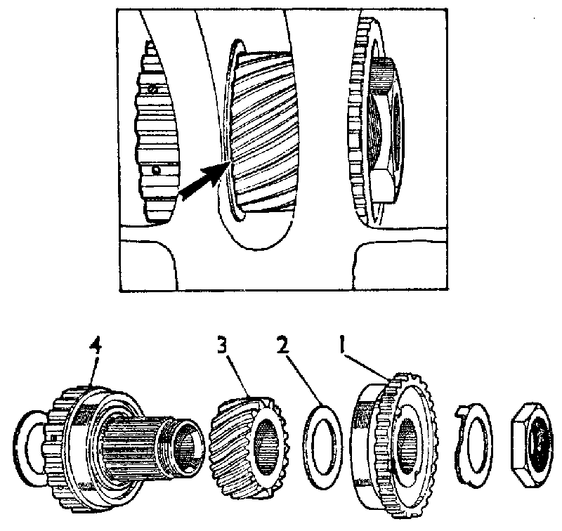
3. Final drive pinion.
4. Top and reverse splines.

fa14.gif
Fig. Fa.14
Using Service tool 18G 1095 to hold the top and reverse spline, when removing the forward clutch hub nut
Shown (inset) correctly assembled with the arrow indicating the chamfer on the pinion

20. Knock back the lock washer on the nut on the forward clutch splines and use Service tool 18G 1095 to hold the top and reverse clutch hub (Fig. Fa.14) and remove the nut with 18G 1096 (Fig. Fa. 15). Drift out the top and reverse clutch hub and lift out the pinion assembly.
21. Remove both the bearings from the centre webs of the transmission case; each bearing must be drifted out on its outer race and from opposing sides of the webs.

Reassembling the transmission unit
Absolute cleanliness is essential, use fuel (petrol) or paraffin (kerosene) where necessary for cleaning. Dry the components with an air pressure line or use non-fluffy rag.
Clean all joint faces and fit new joint washers and oil seals.
After reassembly of each dismantled unit the complete transmission can now be rebuilt.
Lubricate all components with one of the recommended oils, refer to the 'RECOMMENDED LUBRICANTS' chart shown in the 'MAINTENANCE' Section. Ensure that new 'O' rings and seals are well lubricated when reassembling units or rebuilding the transmission assembly.
22. Refit the top and reverse clutch hub bearings to the centre webs of the transmission casing. Drift each bearing on its outer cage into the web until the bearing register contacts the face of the web.
23. Refit the top and reverse clutch hub, together with the final drive gear pinion but without the selective washer. Lightly tighten the forward clutch hub nut until light friction is felt on the bearings when rotating the hub.

fa17.gif
Fig. Fa.17
Using service tool 18G 1095 to hold the top and reverse splines when tightening the forward clutch hub nut

fa18.gif
Fig. Fa. 18
Tightening the forward clutch hub nut with Service tools 18G 1096 1, and 18G 592, 2

24. Check the gap existing between the final drive gear and the forward clutch hub bearing face.
25. Subtract .002 in. (.05 mm.) from the gap measurement and select a washer of this thickness from the range available.
26. Remove the hub and refit the assembly with the selected washer and with the chamfer on the final drive pinion facing the gear train (see Fig. Fa. 16).
27. Use Service tool 18G 1095 to hold the top and reverse clutch splines (see Fig. Fa. 17) and tighten the forward clutch hub nut with Service tool 18G 1096 and 18G 592 (see Fig. Fa.18), to the torque figure given in 'GENERAL DATA'.

fa19.gif
Fig. Fa.19
Holding the forward clutch in position with Service tool 18G 1097

28. Check that there is light friction on the bearings when rotating the hub, i.e. the bearings should have a preload of .002 in. (.05 mm.).
29. Tap up the locking washer.
30. Insert the forward output shaft with its bi-metal washer (see Fig. Fa.9) through the output gear assembly. Ensure that the correct type of reverse shut-off valve is located in the end of the shaft (see item 10), and that the rings on the shaft are in good condition.
31. Position the plastic sleeve over the rings on the forward clutch shaft and refit the forward clutch unit. If an earlier unit is being replaced by one of a later type, the reverse shut-off valve must also be changed (see item 10). Fit Service tool 18G 1097 to retain the correct position of the forward clutch unit (see Fig. Fa. 19).
32. Fit new seals to the valve block connections and fit them into their correct locations in the transmission casing.
If a new transmission casing is being fitted, check the distance from the front flange of the transmission to the face of the centre connection inside the case. See that the correct connections are fitted according to the chart below, or else the valve block may later prevent the front cover from seating properly.

DISTANCE CONNECTIONS
2.25 in. (57.2 mm.) 22A 1336
2.48 in. (62 mm.) 22A 812

fa21.gif
Fig. Fa.21
Engaging the valve block linkage 1 with the spring clip drive mechanism 2 of the later-type governor

33. Reassemble the valve block and servo unit as an assembly, fitting new seals to the inter-connecting pipes.
34. Refit the second, third, and reverse gear bands into the transmission casing.
35. Refit the valve block and the servo unit as an assembly into the transmission case, ensuring correct location of the valve block with the connections in the case and that the governor linkage is positioned over the web in the transmission casing.
36. Locate the bands on the servo struts.
37. Tighten the valve block and the servo unit securing bolts to the torque figure given in 'GENERAL DATA'.
38. Refit the forward clutch apply pipe into its location in the transmission casing.
39. Refit the auxiliary pump pick-up strainer and pipe; secure the pipe with the dowel bolt (fitted with a copper scaling washer). Refit and tighten the strainer securing screw.
40. Fit a new joint washer to the transmission casing. Fit Service tool 19G 1094 and align the pipes (Fig. Fa.20) and remove the tool.
41. Refit the auxiliary pump and governor assembly and engage the valve block linkage with the later-type governor unit as shown in Fig. Fa.21, also ensuring correct alignment with the oil pipes and the forward shaft. The plastic sleeve fitted over the rings on the shaft is for assembly purposes, and will become safely displaced along the forward clutch shaft. Tighten the securing nuts to the torque figure given in 'GENERAL DATA'.
42. Remove the forward clutch retainer-Service tool 18G 1097.

fa20.gif
Fig. Fa.20
Using the positioning fixture Service tool 18G 1094 to ensure correct alignment of the pipes

43. Refit the top and reverse clutch hub washer and the Terrington needle thrust bearing into position with grease.
44. Ensure that the top and reverse clutch friction plates are free to drop before refitting the gear train assembly into the transmission. Correctly position the second, tl-drd, and reverse gear bands in the case and ref it the gear train, using hand pressure only to push it into position. Quick rotation of the input gear will assist in engaging the top and reverse clutch friction plates. When correctly reassembled the dowel bolt will engage easily in the free-wheel support (Fig. Fa. 10).
45. Refit the dowel bolt with a new lock washer.
46. Screw the gear change transverse rod fully into the valve block linkage. Check and reset if necessary the transverse rod adjustment (see Section Fa.2).
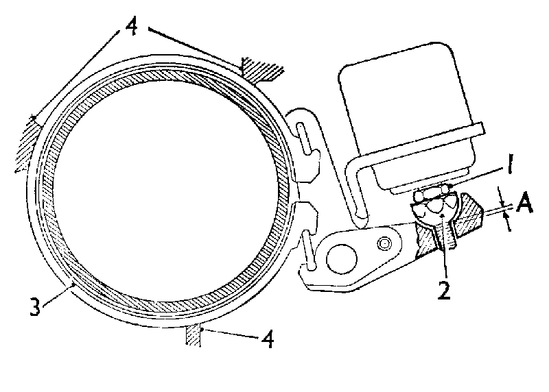
47. Adjust the second, third and reverse servos (see Fig. Fa.24). Slacken the locknut 1 and turn the spherical adjuster 2 until each brake band 3 is in contact with the transmission easing stops 4 and all slack is just eliminated. Turn back the adjuster nine flats to obtain the clearance 'A' and tighten the locknut, which should give the minimum clearance.
48. Fit a new seal to the front cover connection, and refit the cover using a new joint washer. On early units the front cover connection can be rerrioved and therefore requires two oil seals. If the front cover fails to mate correctly with the transmission case check that the correct transmission easing to valve block connections have been fitted as described in item 3 2.
49. Refit the engine oil feed pipe as shown in Fig. Fa.23. On later transmissions refit the valve block connecting pipe through the adaptor hole and screw the adaptor back in.

fa22.gif
Fig. Fa.22
The correct position of the kick-down rod assembly

fa23.gif
Fig. Fa.23
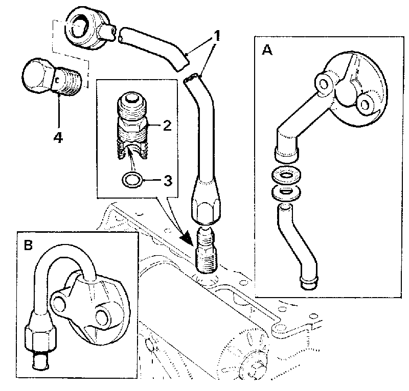
The engine oil feed pipe assembly. Inset 'A' shows the early type assembly. Inset 'B' shows the adaptor used when a later transmission is fitted to an early type engine
1. Engine oil feed pipe.
2. Adaptor.
3. Adaptor 'O' ring seal
4. Banjo union screw.

50. Refit the main oil strainer and pick-up pipe using new seals (if these items were removed), see item 2a.
51. Refit the differential assembly as detailed in Section Fa.16.
52. Refit the engine to the transmission as detailed in Section Aa.4 (if removed see item 2a).
53. Refit the converter and components removed in item 2b see Section Aa.4.
54. Refit the engine/transmission unit to the car as detailed in Section Aa.3.

fa24.gif
Fig. Fa.24
The servo unit band adjustment
A =.040 to.080 in. (1.02 to 2.03 mm.)

fa25.gif
Fig. Fa.25
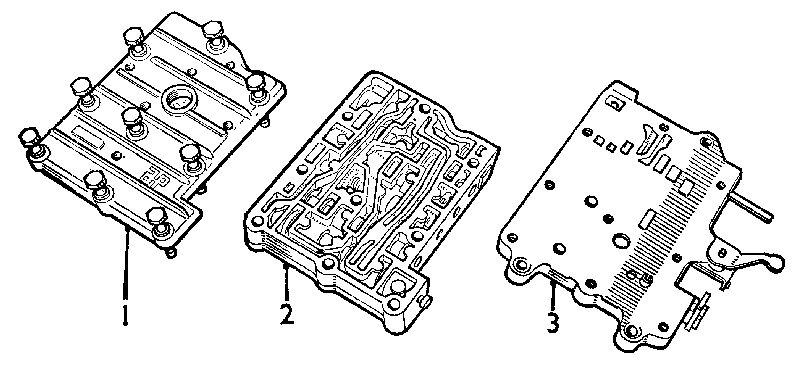
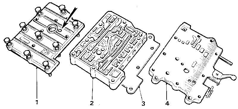
The valve block assembly (Mk. I and II transmissions)
1. Lid.
2. Valve chest.
3. Pipe chest.

Section Fa.7

VALVE BLOCK
(Removing and Refitting)

Early unit (848 c.c. Up to Engine No. 8AH/A/H9733)
The valve block can be removed from the transmission unit with the power unit IN SITU by removing the unit as three individual sections.
It is necessary to clean thoroughly the area around the transmission front cover before any dismantling is commenced, Absolute cleanliness is essential at all times and especially so whilst servicing this unit.

Later 848-c.c. and 998-c.c. units (From Engine No. SAH/A/H9734)

The valve block assembly cannot be removed from the transmission unit with the power unit IN SITU but the lid and valve chest can be removed for dismantling and cleaning. If it is necessary to examine and/or fit new seals to the valve block/servo unit interconnecting pipes or to remove the pipe chest, it is necessary to remove the power unit from the car and remove the converter and housing (see items 25 to 32).

fa26.gif
Fig. Fa.26
The valve block (with inbuilt engagement control and shuttle valves) which is fitted to the Mk. 11 B transmission unit. This unit may be identified by the exhaust hole in the lid (arrowed)
1. Lid.
2. Valve chest.
3. Separator plate.
4. Pipe chest.

fa27.gif
Fig. Fa.27
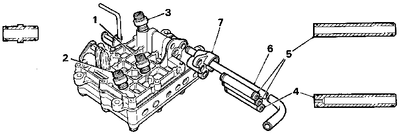
The valve block connections and pipes. Assemble the pipe 4 with its restricted end in the valve block (Mk. I and 11 transmissions only)
1. Connection-top/reverse clutch.
2. Connection-forward clutch.
3. Connection-auxiliary pump (not fitted on Mk. II B units).
4. Connecting pipe with restrictor to reverse servo(pipe without restrictor fitted to Mk. 11 B units).
5. Connecting pipes (to second and third servos).
6. Converter feed pipe.
7. Pipe assembly guide.

Removing (early models)
1. Remove the front grille.
2. Remove the filter assembly as detailed in Section Aa,2.
3. Remove the engine oil feed pipe.
4. Drain the engine/transmission unit.
5. Remove the transmission front cover and valve block connection.
6. Place the gear selector lever in the 'R' position on the quadrant.
7. Remove the bell-crank lever clevis pin. Unscrew and pull out the transverse rod sufficiently to remove the valve block.
8. Loosen the servo unit securing bolts.
9. Remove the valve block assembly as individual components, i.e. the lid, valve chest, and finally (if necessary) the pipe chest (Fig. Fa.25).
The valve block can only be removed as an assembly with the power unit removed from the car.

VALVE CHEST ONLY-'POWER UNIT IN SITU'
Removing (later 848-c.c. and 998-c.c. models)

10. Carry out items 1, 2, and 4.
11. Disconnect the engine oil feed pipe and remove the adaptor. Withdraw the valve block connecting pipe through the adaptor hole.

fa28.gif
Fig Fa.28
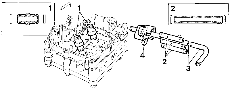
Fhe valve block fitted to Mk. 11 B transmissions (with engagement control valve incorporated in the valve block assembly)
1. Connections (top/reverse clutch and forward clutch).
2. Connecting pipes (to second, third and reverse servos).
3. Converter feed pipes.
4. Guide-converter feed pipe.

fa29.gif
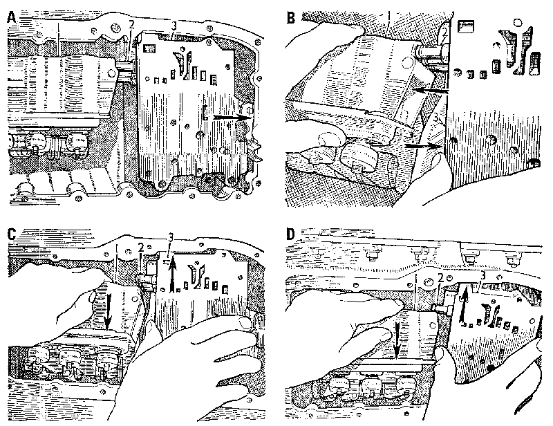
Fig. Fa.29
The removing and refitting sequence of the pipe chest section of the valve block
1. Servo unit.
2. Connecting pipes.
3. Pipe chest.

12. Remove the transmission front cover and manoeuvre the cover upwards and out through the grille aperture.
13. Remove the valve block lid and the valve chest.

Refitting

14. Refitting is a reversal of the removal procedure; take care to locate the selector valve with the linkage and the governor rod with the governor. The flat on the governor valve must face inwards. Tighten all securing bolts to the torque figures given in 'GENERAL DATA'.
15. Ensure that the new joint washer fitted to the filter head/transmission front cover is correctly fitted.
16. Check llie gear change selector lever cable and transverse rod as detailed in Section Fa.2 and adjust if necessary.
17. Refill the, engine/transmission unit with one of the recommended oils (see 'RECOMMENDED LUBRICANTS' chart in 'MAINTENANCE' Section).
Top up to the 'MAX' mark on the dipstick, see the procedure given in Section Aa. 1.

VALVE BLOCK ASSEMBLY REPLACEMENT 'POWER UNIT REMOVED'
Removing (later 848-c.c. and 998-c.c. models)

18. Remove the engine/transmission unit from the car (Section Aa.3).
19. Remove the converter cover, converter and converter housing as detailed in Section Aa.4, items 3 to 11.
20. Drain the engine/transmission unit.
21. Remove the complete filter assembly as detailed in Section Aa.2.
22. Disconnect the engine oil feed pipe and remove the adaptor. Withdraw the valve block connecting pipe through the adaptor hole.
23. Remove the front cover.
24. Disconnect, unscrew, and pull out the transverse rod.
25. Remove the governor control assembly from the transmission case and fit Service tool 18G 1097 to hold the forward clutch (see Fig. Fa. 19).
26. Remove the securing nuts and withdraw the auxiliary pump and governor assembly from the transmission case.

fa30.gif
Fig. Fa.30
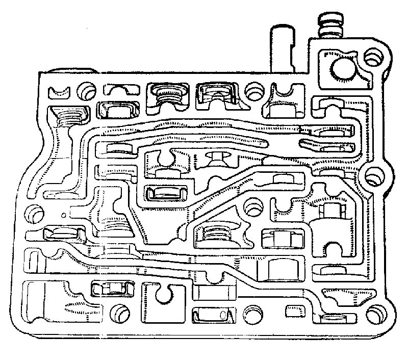
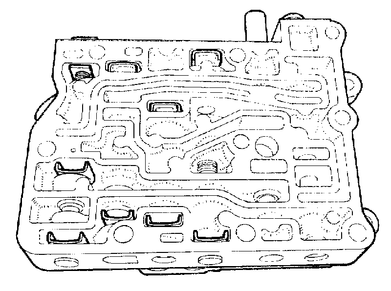
The valve chest with the locations of the valves and components (Mk. I and 11 transmissions)
1. Selector valve.
2. Governor valve.
3. Regulator valve.
4. Tow start valve.
5. Second and top gear valve&
6. Third gear valve.

27. Remove the valve block lid and valve chest.
28. Remove the pipe chest as shown in the operation sequence in Fig. Fa.29 after pulling it outwards to release it from the connections and to disconnect the governor linkage.
29. Refer to Fig. Fa.29.
a. Push the pipe chest fully against the casing.
b. Move the servo unit in the opposite direction until the three pipes are clear of the servo unit.
c. Pull the servo unit outwards and downwards; lift the pipe chest upwards and (when clear), move it so that the pipes are over the top of the servo and the regulator valve lever is clear of the transmission casing.
d. Hold the servo unit down and withdraw the pipe, chest after lifting the linkage over the web in the casing.

Fitting replacement unit
30. Remove the lid and valve chest from the pipe chest of the new unit. Refit these as individual components in the reverse order of the removing procedure, noting the following points.
31. Fit the connections into their locations in the transmission case.
32. Assemble the three pipes into the pipe chest (together with the nylon guide) before refitting the unit to the transmission casing.
33. Carry out operation 14.
34. Position the plastic sleeve over the rings on the forward clutch shaft.
35. Carry out operations 40 to 42 in Section Fa.6.
36. The remainder is a reversal of the removal procedure.

Section Fa.8

VALVE BLOCK
(Dismantling and Reassembling)

Dismantling
NOTE.- Before dismantling the valve block it must be remembered that the valves are selected for each bore. It is of the utmost importance therefore to reassemble each valve into its original bore and position. Cleanliness is essential at all times.
1. If the valve block has been removed as a complete unit, detach the lid and valve chest from the pipe chest. See Fig. Fa.25.
2. Remove the selector and governor valves.
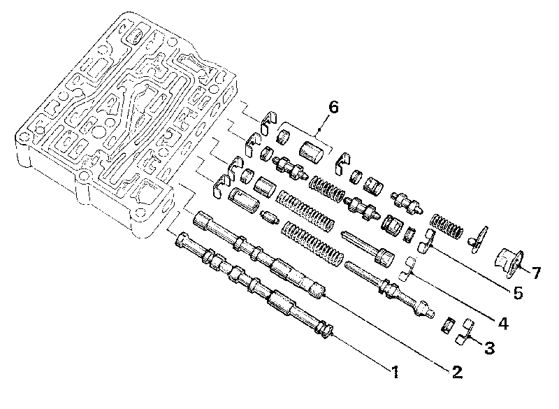
3. Remove the 'C' clips and the plugs. Remove the regulator valve, spring, and reverse booster piston assembly.
4. Remove the 'C' clip and the plug. Remove the tow-start valve, spring, and spring retainer.

fa31.gif
Fig. Fa.31
The valve chest with the 'C' clips correctly positioned (Mk. I and 11 transmissions)

5. Remove the 'C' clips and the plugs. Remove the second and fourth gear valves, spring, and booster piston.
6. Remove the 'C' clip and plug. Remove the third gear valve booster piston, spring, spring retainer and the plastic plug.

fa32.gif
Fig. Fa.32
The valve chest fitted to mk. 11 B transmission showing the locations of the valves and components

1. Selector valve.
2. Governor valve.
3. Regulator valve components.
4. Engagement control valve components
5. The components of the second and top gear valves.
6. One-way dump valve and stop (plug)
7. Third gear valve components

fa33.gif
Fig. Fa.33
The locations of the 'C' clips in the valve chest (Mk. 11 B transmission)

Inspecting
Clean all parts thoroughly in clean fuel (petrol) or paraffin (kerosene) and dry off using an air pressure line.
Check for burrs on the valves and valve chest and for sticking valves. Place all components in automatic transmission oil before reassembling to the valve block.

Reassembling
7. Reassemble each valve assembly in the reverse order of dismantling (see Fig. Fa.30). Check that the 'C' clips and plugs are correctly located in the valve chest (see Fig. Fa.31).

Section Fa.9

VALVE BLOCK-WITH INBUILT ENGAGEMENT CONTROL AND SHUTTLE VALVES

(Dismantling and Reassembling)

Dismantling
NOTE, -Before dismantling the valve block it must be remembered that the valves are selected for each bore. it is of the utmost importance therefore to reassemble each valve into its original bore and position. Cleanliness is essential at all times.
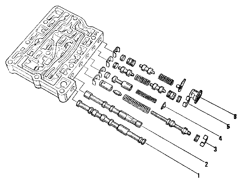
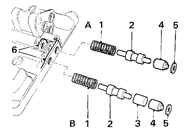
1. If the valve block has been removed as a complete unit, which is essential if the shuttle valves are to be di-smantled, detach the lid and valve chest from the pipe chest and also take out the separator plate and flap valve.
2. Pull out the selector and governor valves.
3. To remove the regulator valve components, pull out both 'C' clips and extract the plugs, the regulator valve, spring and reverse booster piston.
4. Pull out both the 'C' clips which secure the engagement control valve components, and extract the plain plug, the plug with the extended stop, the spring and the valve.
5. Pull out both the retaining 'C' clips and extract the plugs, second and top gear valves, spring and booster piston.
6. Pull out the end 'C' clip and extract the plug and the one-way dump valve. Withdraw the centre 'C'-clip and remove the third gear valve with the booster piston, spring, spring retainer and the plastic plug.

fa34.gif
Fig. Fa.34
'A' Third gear shuttle valve assembly
'B'-Reverse gear shuttle valve assembly
1. Spring.
2. Shuttle valve.
3. Engagement piston.
4. Abutment.
5. Washer.
6. Washer locating ribs.

fa35.gif
Fig. Fa.35
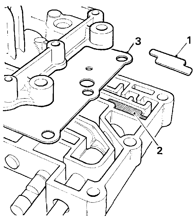
It is essential that the flap valve 1 is positioned flat on its seatings 2 before the separator plate 3 is located and the valve block is reassembled

ENGAGEMENT CONTROL SHUTTLE VALVES
7. From the back of the pipe chest depress in turn the abutment of each of the shuttle valve components sufficiently to release the retaining washer, then extract the abutment, engagement piston (reverse gear shuttle), shuttle valve and the spring.

Inspecting
Clean all parts thoroughly in clean fuel (petrol) or paraffin (kerosene) and dry off using an air pressure line.
Check for burrs on the valves and valve chest and for sticking valves. Place all components in automatic transmission oil before reassembling them into the valve block.

Reassembling
8. Reassemble for each valve assembly into its correct bore in the reverse order of dismantling (see Fig. Fa.32). Check that the 'C' clips and plugs have been correctly located in the valve chest, as shown in Fig. Fa.33, and then the retaining washers of the shuttle valves are properly seated in their correct locations (see Fig. Fa.34).

9. When reassembling the complete valve block see that the flap valve is fitted, lying flat, in its correct location behind the selector valve as shown in Fig. Fa.35, and that the separator plate is fitted between the valve chest, and the pipe chest.

Section Fa.10

AUXILIARY PUMP AND GOVERNOR

Removing
1. Remove the engine/transmission unit from the car as detailed in Section Aa.3.
2. Remove the governor control assembly from the transmission case and fit Service tool 18G 1097 (see Fig. Fa.19).
3. Remove the securing nuts and pull the auxiliary pump and governor assembly from the transmission case.

Dismantling
4. Remove the speedometer drive assembly.
5. Remove the set screws and bolt. Pull out the governor centre shaft, and lift away the governor assembly together with one of the auxiliary pump gears.
6. Remove the circlip, lift off the auxiliary pump gear, and remove the governor.
7. Lift out the governor bearing trunnions and washer.
8. Remove the second auxiliary pump gear from the auxiliary pump housing together with its thrust washer; the earlier type cover is fitted with a bi-metal thrust washer with a plain bush fitted in the housing while the later type cover has a flanged bush and a steel thrust washer, see Fig. Fa.37.

fa36.gif
Fig. Fa.36
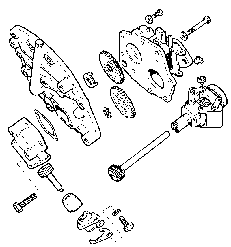
The speedometer drive, auxiliary pump gears and governor assembly components

fa37.gif
Fig. Fa.37
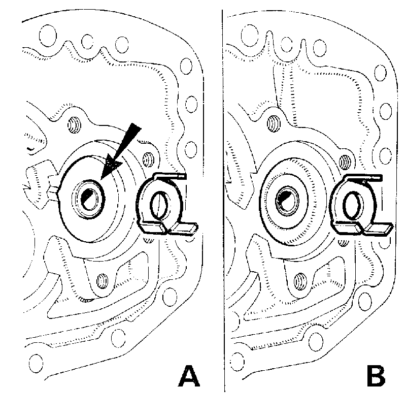
Both types of auxiliary pump housing.
'A' shows the later type housing with a flanged bush (arrowed) and steel thrust washer.
'B' shows the early type housing with a plain bush and bi-metal thrust washer

Inspecting
Examine all components for wear or damage. All units except Mk. II B. Check the condition of the bi-metal thrust washer; if it has broken up and caused the bush in the housing to move deeper into its bore, replace the gears and housing assembly with the Mk. 11 B assembly which has a flanged bush and a steel thrust washer, see Fig. Fa.3 7.

Reassembling
9. Reassemble the auxiliary pump gear with its thrust washer to the pump casing (see Fig. F a.3 7).

fa38.gif
Fig. Fa.38
Centralizing the pump and governor unit 1 with the end cover 2 using Service tool 18G 1106 (arrowed)

10. Refit the governor auxiliary pump gear and circlip. Ensure that both gears are seating correctly and will rotate freely after assembly.
11. Refit the governor assembly to the auxiliary pump and refit the centre shaft.
12. Use Service tool 18G 1106 to centralize the auxiliary pump and governor unit with the end cover, tighten the securing bolts to the torque figure given in 'GENERAL DATA' and remove the Service tool.
13. Refit the speedometer drive assembly, with a new joint washer.

Refitting
14. Carry out the instructions given in Section Fa.6, items 40 and 42.
NOTE.-See 'GENERAL DATA' for all torque figures.

Section Fa.11
FORWARD CLUTCH

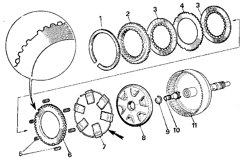
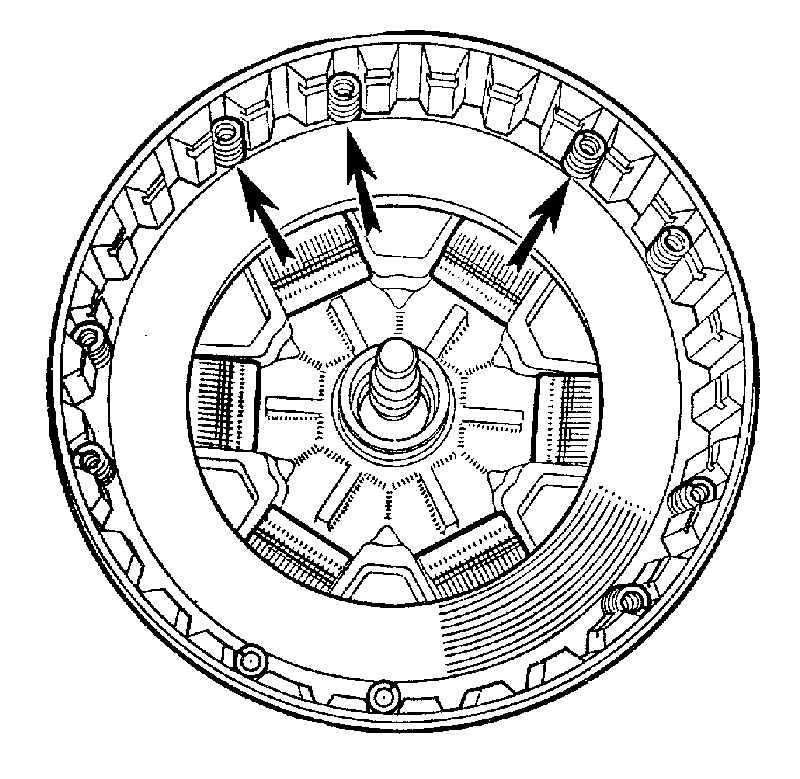
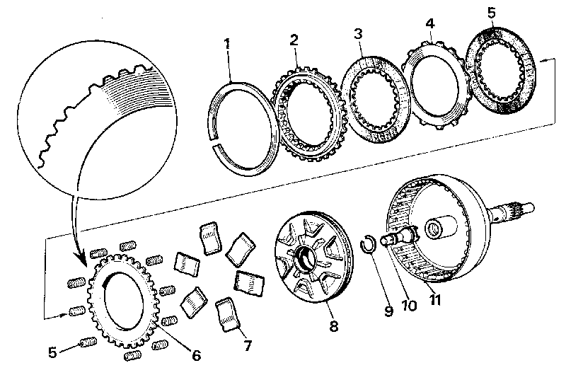
Two types of clutch assembly have been fitted. The earlier type has 47 teeth and is shown in Fig. Fa.4 1. This has now been replaced by a clutch having 30 teeth which is shown in Fig. Fa. 43. The two clutches are interchangeable as complete assemblies, although the individual components are not.

fa39.gif
Fig. Fa.39
Fitting the forward clutch piston using Service tool 18G 1102
1. Forward clutch.
2. Service tool 18G 1102.
3. Forward clutch piston.

fa40.gif
Fig. Fa.40
The fitted position of the toggles and spring ring (fitted to very early units). The arrow indicates location of spring ends exactly opposite the only five tooth section of the clutch unit

NOTE.- Later 30 tooth forward clutches are fitted with a modified reverse shut-off valve piston (see item 1 0, Section Fa.6). If fitting a new clutch having the modified piston, the reverse shut-off valve in the forward output shaft must also be replaced by one of the modified types.

Removing
1. Carry out the operations given in Section Fa.6, items 1 and 4 to 9.

Dismantling
2. Remove the retaining circlip or Spirolox ring.
NOTE.-Mark the retainer plate and steel clutch plate to assist when reassembling.
3. 30 TOOTH CLUTCH: Remove and discard any shims which have been fitted to rectify clutch plate end-float. A new method of controlling clutch plate end-float using end and intermediate steel plates of varying thicknesses together with a wider section retaining circlip was introduced at the Engine Numbers given below.
Commencing Engine Numbers: 85H-285E-H347, 99H-28SE-H3832, and 99H471E-H1421.
NOTE.- Whenever a transmission is dismantled prior to the above Engine Numbers, the assembly may be brought up to the latest specification. Always check the specification of a new forward clutch unit taken from stock; fit the relevant parts required and check the end-float adjustment before fitting.
Refer to 'Adjusting' and the chart giving the range of plates available.

fa41.gif
Fig. Fa.41
The early-type (47-tooth) forward clutch components. The arrow indicates the spring ring fitted to very early units only
1. Circlip (replacing Spirolox ring).
2. End plate.
3. Clutch plates (paper faced).
4. Intermediate plate.
5. Piston return springs (6).
6. Pressure plate.
7. Toggles.
8. Piston.
9. Circlip-reverse shut-off valve.
10. Reverse shut-off valve.
11. Forward clutch unit.

4. Lift out the piston return springs and pressure plate.
5. Remove the spring ring (if fitted) and toggles (see Fig. Fa.41).
6. Use an air pressure line to blow out the piston.
7. Remove the circlip and lift out the reverse shut-off valve piston, which should be identified as detailed in item 10 of Section Fa.6, for reassembly.

Inspecting
Check all parts for wear and renew if necessary. Check the reverse shut-off valve oil seals and renew if necessary.

Reassembling
8. Refit the reverse shut-off valve piston of the correct type, and fit a new circlip.
9. Assemble the seal onto the piston with the lips of seal facing inwards and lubricated with one of the recommended oils, see 'RECOMMENDED LUBRICANTS'.
10. Insert Service tool 18G 1102 into the clutch unit and press the piston through the tool until it is fully into its bore, see Fig. Fa.39.

fa42.gif
Fig. Fa.42
The fitted position of the toggles and springs of the 30-tooth clutch

fa43.gif
Fig. Fa.43
The (30-tooth) forward clutch components
1. Circlip (replacing Spirolox ring).
2. End plate.
3. (Clutch plates (paper faced).
4. Intermediate plate.
5. Piston return springs (10).
6. Pressure plate.
7. Toggles.
8. Piston.
9. Circlip-reverse shut-off valve.
10. Reverse shut-off valve.
11. Forward clutch unit.

47-TOOTH CLUTCH. Assemble the toggles and spring ring (early udts) with the end of the spring-ring located as shown in Fig. Fa.40, and with the cut-out tooth on the pressure plate in the relative position to the ends of the spring ring (Fig. Fa.41). Assemble the first friction plate and the piston return springs.
12. 47-TOOTH CLUTCH. Assemble the remainder of the components as shown in Fig. Fa.41 with the six recessed teeth on the end plate positioned relative to the piston return springs.
NOTE.- Since selective end and intermediate plates are not available for the 47 tooth clutch unit, the later type 30 tooth clutch must be fitted as a replacement if the clutch plate end-float is not within the tolerance allowed in the 'Adjusting' procedures given below.
13. 30-TOOTH CLUTCH. Assemble the toggles, pressure plate and the piston return springs, see Fig. Fa.42.

fa44.gif
Fig. Fa.44
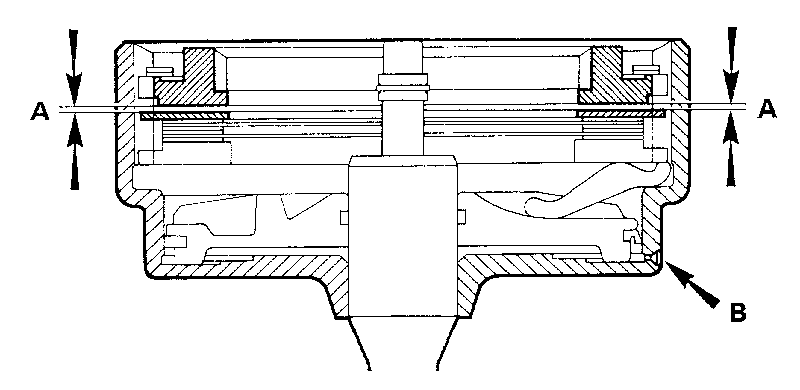
Check the clearance between the end and intermediate-plates with feeler gauges 'A'= 0.010 to 0.035 in. ( 0.25 to 0.9 mm.)
Arrow 'B' shows the drain hole on later-type clutch unit

14. Refit the remaining components in the following order for the purpose of CHECKING THE END-FLOAT ADJUSTMENT ONLY.
a. Refit the two paper-faced plates together.
b. Refit the intermediate plate, end plate and the retaining cirelip.

Adjusting
15. Check with feeler gauges the clearance 'A' between the intermediate plate and the end plate, see Fig. Fa.44. The end-float required is between .010 and .035 in. (.25 and .9 mm.), proceed with item 16 if adjustment is required.
NOTE.--Shims MUST NOT be fitted to rectify end-float.
16. Measure the thickness of the intermediate and end plates and from this measurement, select from the chart below the correct thickness plate(s) to rectify the end-float to within the tolerance given in item 15.

Intermediate and end plate chart
PLATETHICKNESSPART NO.
Intermediate0.064 in. (1.70 mm.)27H 7722
Intermediate0.074 in. (1.88 mm.)37H 7033
End0.342 in. (8.22 mm.)27H 7724
End0.362 in. (9.21 mm.)37H 7032

17. Reassemble the components into the clutch unit in the order shown in Figs. Fa.41 and Fa.43. If a Spirolox retaining ring has been fitted, it should be replaced with a solid type circlip, preferably the later (wider section) type, Part No. 37H 7031.

Refitting
18. Carry out the operations given in Section Fa.6 items 30 and 38 to 42.
19. Refit the governor linkage.

Section Fa. 12
GEAR TRAIN
Two types of bevel gear train assemblies have been fitted. The later Mk. II type is fitted to all transmission units from Engine Nos. 8AH-A-H10554, 9AG-A-H1603, and the 99H series from outset.

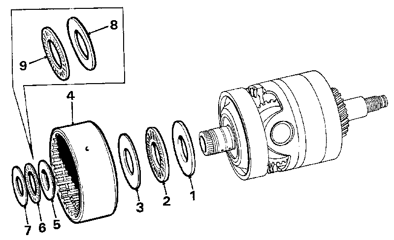
Special equipment is used to obtain the correct backlash for the various gears when assembling the gear train; it is not possible to assemble the gear train with this equipment. The only washer in the gear train that is not selective and can be renewed is the forward output gear bi-metal washer (see Figs. Fa.50 and Fa.52-item 8). In the event of failure of any part of this unit a new gear train assembly must be fitted.

Interchangeability of assemblies
In the event of the Mk. I gear train assembly not being available, the later type Mk. II assembly may be fitted-together with the following components which must be used with the Mk. II unit and replaces similar parts used in the Mk. I transmission unit.

Replacement parts
Freewheel housing.
Forward shaft and thrust washer.
Top/reverse clutch with thrust bearing and washers.*
Top/reverse clutch hub with thrust bearing and washer.
*Only required if prior to Transmission No. E04859.

Removing
1. Carry out the operations given in Section Fa.6, items 1 to 2b and 12.

Dismantling
Dismantling of the gear train is necessary only if the forward output gear bi-metal washer is to be replaced.

fa45.gif
Fig. Fa.45
Removing or refitting the top and reverse clutch
1. Selective washer.
2. Needle thrust bearing.
3. Thrust washer.
4. Top and reverse clutch.
5. Thrust washer (stepped) - later type.
6. Needle thrust bearing - later type.
7. Thrust washer.
8. Thrust washer.
9. Needle thrust bearing.

fa46.gif
Fig. Fa.46
Removing the third speed reaction gear. The arrows indicate the bi-metal washer locations
1. Bi-metal washer.
2. Shim (if fitted).

fa47.gif
Fig. Fa.47
Removing the input gear 1,
the first gear free-wheel reaction member 2,
and the needle-roller bearing 3

2. Remove the top and reverse clutch.
NOTE.-For top and reverse clutch dismantling and reassembling see Section Fa.13.
3. Remove the thrust race and washers (Fig. Fa.45).
4. Remove the third gear reaction member together with its thrust washer and shim (if fitted) (Fig. Fa.46).
5. Remove the input gear, and pull off the first gear free-wheel reaction member and needle-roller bearing (Fig. Fa.47).
6. Knock back the lock washers and remove the first gear free-wheel housing set screws.
7. Pull out the first gear free-wheel assembly, input gear, Torrington thrust race, and washer (Fig. Fa.48).
NOTE. - For first gear free-wheel assembly dismantling and reassembling see Section Fa. 15.

8. a. Dismantling of the Mk. 11 gear train assembly is given below in items 9 to 15, with the reassembly sequence in items 20 to 32.
b. To dismantle the Mk. I gear train assembly, as shown in Figs. Fa.49 and Fa.50, refer to items 16 to 19 with the reassembly sequence given in items 33 to 36.

Dismantling gear train (Mk. II)
9. Remove the spindle end cover circlips and covers; remove the small locking circlip and unscrew the spindle locking screws.
10. Hold the unit on its side until the locking ball rolls out from the hole in the planetary gear spindle. Repeat this operation on the other side.
11. Insert Service tool 18G 1093 A into the forward output gear and through the complete assembly to assist the dismantling procedure.
12. Screw the Service tool adaptor 18G 284 AJ into one of the planetary gear spindles and using Service tool 18G 284 pull the spindle from the gear. Repeat this operation with the other spindle and withdraw the needle -roller bearings.

fa48.gif
Fig. Fa.48
Removing the one-way clutch and the input gear with its Torrington needle thrust bearing and washer

13. Knock back the locking tabs and remove the strap securing bolts.
14. Ease the strap off the dowels and lift the complete assembly from the carrier.
Retain the respective positions of each planetary gear thrust washer with the carrier.
15. Dismanting the assembly, ensuring that all components are retained in their respective positions for reassembly (see Fig. Fa. 5 1).

Dismantling gear train (Mk. 1)
16. Check the markings on the carrier and the bearing caps, i.e. marked NIL or with the letter 'O'. These are reference marks to fitting dimensions and the caps must be refitted in their original positions as indicated by the markings on reassembly of the unit.
17. Knock back the locking tabs and remove the bearing cap bolts and the strap securing bolts. Lift out the forward output gear, reverse output gear, and the pinions.
18. Lift off the thrust bearings, pinions, and thrust washers.
19. Lift off the forward output gear and thrust washer, the reverse output gear, thrust washer, and thrust race.

Inspecting
Clean and examine all parts for wear. Fit a new bi-metal washer to the forward output gear if required and renew if necessary the Torrington needle-thrust races. Fit new rubber seals and replace the locking plates. Check that the internal bush of the reverse output shaft has not turned and shut off the output feed.
NOTE.- Use petroleum jelly when reassembling to secure the various thrust washers and needle thrust races in position.

fa49.gif
Fig. Fa.49
Removing the forward and reverse output gears, and the planetary gears from the carrier

fa50.gif
Fig. Fa.50
The early-type gear train completely dismantled
1. Gear carrier.
2. Planetary gears.
3. Forward output gear.
4. Reverse output gear.
5. Steel washer (reverse output gear).
6. Planetary gear washers.
7. Steel shim (forward output gear).
8. Bi-metal washer (forward output gear).

fa51.gif
Fig. Fa.51
The later-type gear train, with the forward and reverse output gears and the planetary gears removed from the carrier

fa52.gif
Fig. Fa.52
A dismantled view of the later-type gear train assembly

1. Gear carrier. 2. Planetary gears. 3. Forward output gear. 4. Reverse output gear. 5. Steel washer (reverse output gear).
6. Planetary gear washers.
7. Steel shim (forward output gear).
8. Bi-metal washer (forward output gear).

Reassembling gear train (Mk. II)
20. Assemble the forward output gear with its bi-metal washer and the .004 in. (.10 mm.) shim (if fitted) interposed between the bi-metal washer and the carrier (see Fig. Fa.52).
Assemble the reverse output gear with its Torrington needle thrust bearing and steel washer.
21. Insert Service tool 18G 1093A through the forward output gear and the assembly to ensure correct alignment.
22. Check and reset the timing of the gear train (see Fig. Fa.53) by rotating the planetary gears until the tinting marks are in alignment.
23. Retain the timed position of the gear train and refit to the carrier ensuring that both timing marks align with the dowel surface of the carrier.
24. Refit the planetary gear needle-roller bearings and tap in the spindles (with the hole on the centre of the spindle facing downwards).
25. Insert a ball into each spindle and screw in the locking screws. Refit the locking screw circlips, end covers, and the cover circlips.
26. Assemble the third speed reaction gear with its bi-metal washer fitted with the white metal face towards the reverse output gear (see Fig. Fa.54) and with the steel shim(s) located between the bi-metal washer and the gear.
Retain each washer and shim in position with petroleum jelly and refit the assembly to the gear train (see Fig. Fa.54).

fa54.gif
Fig. Fa.54
Refitting the third speed reaction gear with its bi-metal washer, locations indicated by arrows
1. Bi-metal washer.
2. Shim (if fitted).

27. Assemble the bevel input gear with its Torrington needle thrust bearing and selective steel washer (see Fig. Fa.48).
28. Refit the one-way clutch to the gear train housing (Fig. Fa.48), tighten the securing bolts, and tap up the locking plate tabs.
29. Refit the free-wheel support.
30. Refit the input gear and needle-roller bearing (see Fig. Fa. 55).
31. Refit the top and reverse clutch with its selective steel washer and needle thrust bearing onto the reverse output shaft. Use the correct diameter thrust washer and needle bearing required for the particular type of clutch and gear train assembly fitted.

fa53.gif
Fig. Fa.53
Timing the gear train

fa55.gif
Fig. Fa.55
Refitting the input gear 1,
the first gear free-wheel reaction member 2,
and the needle-roller bearing 3

fa56.gif
Fig. Fa.56
Checking that the end of the reverse output shaft 1 is level with the internal face of the top and reverse clutch 2

Mk, 11 GEAR TRAIN ASSEMBLY.
When the second type clutch (with annular groove) is fitted, use the larger diameter (stepped type) thrust washer 5 and needle thrust bearing 6, see Fig. Fa.45.

Mk, I GEAR TRAIN ASSEMBLY.
When either clutch assembly (first or second type) is fitted, use the small diameter thrust washer 8 and needle thrust bearing 9, see Fig. Fa.45.
32. Check across the splined end of the reverse output shaft and the adjacent face of the top and reverse clutch (Fig. Fa.56). Both faces must be exactly level with no gap, to ensure that the third speed reaction gear has no end-float and the correct backlash is maintained. If both faces are not level, remove and measure the thickness of the selective steel washer fitted in item 31 and fit the correct selective washer from the range available (see washer chart below).

Selective washer sizesPart Nos.
.076 to .078 in. (1.93 to 1.98 mm.)22G 748
.072 to .074 in. (1.83 to 1.88 mm.)22G 749
.068 to .070 in. (1.73 to 1.78 mm.)22G 750
.064 to .066 in. (1.63 to 1.68 mm.)22G 751

Reassembling gear train (Mk. I)

33. Carry out items 20 to 23 with the following exceptions: Refer to Fig. Fa.50, and use Service tool 18G 1093 when reassembling this early-type gear train.
34. Refit the bearings caps to their respective positions (see markings) and using new locking plates, refit and tighten the bearing cap and carrier bolts to the torque figure given in'GENERAL DATA'.
35. Carry out items 26 to 3 1.
36. Carry out item 32 to determine whether the splined end of the reverse output shaft and the face of the top and reverse clutch are level (see Fig. Fa.56), if they are not, fit the correct selective washer from the range available (see washer chart below).
Note that the selective washers for the early units are not interchangeable with those fitted to later units.

Selective washer sizesPart Nos.
.116 to .118 in. (2.95 to 3.0 mm.)22A 777
.112 to .114 in. (2.8 5 to 2.9 mm.)22A 778
.108 to .110 in. (2.74 to 2.79 mm.)22A 779
.104 to .106 in. (2.64 to 2.69 mm.)22A 780

Refitting

37. Carry out the operations given in Section Fa.6, items 44 and 45. The remainder is a reversal of the removal procedure.
38. Refit the power unit to the car as detailed in Section Aa.3.

Section Fa. 13

TOP AND REVERSE CLUTCH
Two types of clutch units have been fitted, the later (second type) is identified by the annular groove machined in the clutch drum. This unit has a shortened flange above the piston return spring retaining cirelip to enable it to be suitable for fitment to both the Mk. I and II bevel gear train assemblies.

This unit is fitted to all transmissions from Transmission No. E04859 and can be used for replacement on all Mk. I and II gear train assemblies from the following Engine Nos. 9AG-A-H1630 and the 99H engine range from outset. Fit the first type clutch when replacement is required on Mk. I transmissions prior to the above change points.

Removing

1. Carry out the operations given in Section Fa.6, items 1, 2b, and 12.
2. Remove the top and reverse clutch from the gear train together with the Torrington needle thrust bearing and the steel washer.

fa57.gif
Fig. Fa.57
The top and reverse clutch components
1. Housing.
2. Reverse gear booster piston.
3. Top gear cylinder.
4. Top gear piston.
5. Piston return spring.
6. Spring retainer.
7. Spirolox retaining ring.
8. Pressure plate (thin).
9. Separation spring rings.
10. Clutch plates (paper-faced).
11. Pressure plate (intermediate).
12. End plate.
13. Spirolox retaining ring.

Dismantling
3. Remove the Spirolox retaining ring.
4. Remove the retainer plate.
5. Lift out the paper plate, spring ring, steel plate, paper plate, spring ring, and the thin steel plate.
6. Remove the circlip, spring retainer, and the piston return coil spring.
7. Lightly shock the assembly against a flat surface to remove, the top gear piston and cylinder.
8. Refit the reverse (booster) piston into the bore, easing the piston ring into the bore with a screwdriver.
9. Fit Service tool 18G 1103 into the clutch unit and holding these together, lightly shock the assembly against a flat surface to remove the reverse booster piston.

Inspecting
Check all parts for wear and renew if necessary. Renew the oil seals in the pistons. Check the piston ring gap which must be .016 to 0.20 in. (.4 to .51 mm.), for both rings when fitted in their respective bores.

Reassembling
10. Refit the reverse gear booster piston with the boss facing outwards, using Service tool 18G 1103 (see Fig. Fa.58).
11. Refit the top gear piston into its cylinder with the boss facing outwards.
12. Fit the top gear piston and cylinder into the clutch housing, with the cut-aways on the rear outer edge of the cylinder opposite the holes in the clutch housing.

fa58.gif
Fig. Fa. 58
Using Service tool 18G 1103 (2) to remove or refit the reverse gear piston (3) to the top and reverse clutch unit (1)

fa59.gif
Fig. Fa.59
The fitting relationship of the servo levers with the reaction levers and struts

13. Refit the top gear piston return spring, spring retainer, and circlip.
14. Refit the clutch plates in the assembly order shown in Fig. Fa.57, with the cut-away portion of the steel plates in alignment.
15. Refit the retainer plate and circlip.
NOTE. - Before refitting the clutch unit, ensure that the friction plates are free to drop.

Refitting
16. Carry out the operations given in Section Fa. 12, items 31 and 32.
17. The remainder is a reversal of the removal procedure.

Section Fa.14

SERVO ASSEMBLY

Removing
1. Carry out the operations given in Section Fa.6 items 1 to 13.
2. Remove the servo unit from the valve block assembly.

Dismantling
3. Remove the centre shaft and lift out the servo levers, reaction levers, washers, and struts.
4. Hold the servo cover and release the securing screws and the cover.
5. Lift out the springs and pistons.

Inspecting
Check all parts for wear and renew if necessary.

Reassembling
6. Lubricate the seals and fit the pistons into the correct bores (lips of seals facing downwards).
7. Assemble the springs and cover.
8. Hold the cover in position and fit the drive screws.
9. Assemble the struts, washer(s), reaction levers, and servo levers in the reverse order of dismantling (Figs. Fa.59 and 61).
10. Insert the centre shaft with the cutaway in the shaft correctly positioned.

Refitting
11. Carry out the operations detailed in Section Fa.6, items 33 to 48, 53, and 54.

fa60.gif
Fig. Fa.60
The servo unit components

fa61.gif
Fig. Fa.61
The brake band and struts correctly positioned

fa62.gif
Fig. Fa.62
The one-way clutch removed from the gear train, with the input gear, bearings and thrust washer shown in assembly sequence

Section Fa.15

FIRST GEAR FREE-WHEEL ASSEMBLY (ONE-WAY CLUTCH)

Removing
1. Carry out the operation given in Section Fa.61 items 1, 2b, and 12.
2. Remove the first gear free-wheel reaction member.
3. Knock back the locking plate tabs and remove the retaining bolts and the first gear free-wheel (one-way clutch) from the housing.

Dismantling
4. Remove the circlip.

fa63.gif
Fig. Fa.63
The components of the new one-way clutch

5. Lift out the spring ring, first gear free-wheel intermediate spring ring, and thrust bearing (see Fig. Fa.63).

fa64.gif
Fig. Fa.64
Fitting the one-way clutch with the lip (arrowed) correctly positioned uppermost

Inspecting
Check all parts for wear and renew if necessary.

Reassembling
6. Reassemble the thrust bearing, intermediate spring ring, first gear free-wheel (lip facing outwards, see Fig. Fa.64), spring ring, and refit the circlip.

Refitting
7. Refitting is a reversal of the removing procedure.

fa65.gif
Fig. Fa.65
The differential components with the arrow indicating the alignment slot in the spacer

Section Fa. 16

DIFFERENTIAL ASSEMBLY

Removing
1. Remove the engine and transmission from the car (see Section Aa.3).
2. Drain the engine/transmission unit.
3. Use Service tool 18G 1100 to hold the driving flanges and remove the centre securing bolts. Withdraw the flanges from the splined shafts.
4. Knock back the lock washers and remove the nuts from the final drive housing.
5. Remove the securing screws and pull the kick-down linkage assembly clear of the transmission case.
6. Remove the two set screws securing the end cover to the transmission, and remove the final drive and housing assembly (Fig. Fa. 1 2).
7. Remove the remaining securing bolts from the end cover and remove the cover and the adjustment shims.

Dismantling
8. Remove the differential unit from its casing.
9. Withdraw the oil seal housing, remove the bearings using Service tool 18G 2.
10. Knock back the locking plate tabs and remove the bolts securing the driving gear to the cage. Mark the gear and cage so that they can be refitted in their original positions.
11. Separate the driving gear from the cage and remove the differential gear and thrust washer from the driving gear.
12. Tap out the roll pin and remove both pinions and thrust washers, pinion spacer, and the other differential gear and thrust washer.

Inspection
Clean and examine the components for wear and fit new parts as necessary.

NOTE. - If any component has suffered damage with the result that swarf has been introduced into the lubricating system the automatic transmission must be removed (Section Aa.4) and dismantled as detailed in Section Fa.6.
This also applies if fitting a replacement drive gear pinion into the transmission unit.
Absolute cleanliness is essential.

Reassembling
13. Reassembly is a reversal of the dismantling procedure.
Make sure that the differential gear thrust washers are fitted with their chamfered bores against the machined faces of the differential gears. Refit all components in their original positions.

Refitting
14. Refit the differential unit into the transmission case and push the assembly towards the converter, with the slot in the spacer in alignment with the dowel in the transmission case (Fig. Fa.65). Fit a new joint washer coated with Hylomar jointing compound. Ensure that the oil seal is pressed squarely against the face of the spacer and refit the differential housing, fit new locking plates, and lightly tighten the securing nuts.

ADJUSTMENT
15. Refit the end cover without a joint washer but with the original adjustment shims, tighten the cover bolts evenly and sufficiently only for the cover register to nip the bearing outer race; overtightening will distort the flange.
16. Take a feeler gauge measurement at varying positions between the side cover flange and the differential housing, any variations in measurement will indicate that the cover bolts are not evenly tightened. Adjust the cover bolts accordingly until identical measurements can be obtained. The compressed thickness of a new cover joint washer is .007 in. (.178 mm.) and the required preload on the bearings is .002 in. (.051 mm.). The correct gap is therefore .009 in. (.229 mm.), any deviation from this figure must be made up by adding or subtracting shims.

EXAMPLE: If the feeler gauge measurement is .005 in. (.127 mm.), add a shim of .004 in. (.10 mm.) thickness between the bearing and the end cover.
17. Remove the end cover, fit shims as required, and refit the cover with a new joint washer coated with Hylomar jointing compound. Tighten the differential housing nuts and the cover bolts to the torque figures given in 'GENERAL DATA'. Tap up the locking plate tabs, except the nut which accepts the exhaust pipe bracket (fitted when the engine is in the car).
18. Lubricate the driving flange oil seal and refit the flanges making sure that the split collets are correctly located inside the flanges. Fit new rubber seals to and refit the central securing bolts. Hold the flanges with Service tool 18G 1100 and tighten the flange bolts with Service tool 18G 372 to the torque figure given in 'GENERAL DATA'
19. Refit the governor control linkage to the transmission case with a new washer. Ensure the lever is positioned correctly, relative to the governor (see Fig. Fa.22).
20. Carry out the 'Refitting' instructions given in Section Aa. 3.

Section Fa. 17
LUBRICATION RESERVOIR
(IDLER GEAR BEARING)

To provide additional lubrication to the idler gear bearings, a transmission case incorporating a 'cast in' oil reservoir was introduced at the following Engine Nos: 8AH-A-H11338, 99H-143-H5983 and 99H-147-H834. Earlier units should be modified by fitting a separate reservoir as detailed below.

Fitting
1. Remove the engine/transmission from the car (see Section Aa.3).
2. Remove the transmission unit from the engine (see Section Aa.4).
3. Refer to Fig. Fa.66. Measure down from the joint face on the outside of the casing 3 19/32 in. (91.3 mm.) and from this point mark a horizontal line across the casing a indicated. Place the reservoir upside-down on the outside of the casing with its spigot located in the idler gear bearing bore and with its securing lug positioned centrally over the horizontal marking. Indent this position; remove the reservoir and drill through the casing using a 9/32 in. (7.14 mm.) drill; place a piece of Plasticine inside the casing where the hole will break through to trap any swarf.

fa66.gif
Fig. Fa.66
The reservoir fitted upside-down on the outside of the casing with the marked line shown through the centre of the securing lug. An arrow indicates the drilling location. 'A' = 3 19/32 in. (91.3 mm.)

4. If necessary, file the reservoir casting to ensure that it will fit snugly against the transmission casing.
5. Smear the reservoir spigot with Hylomar jointing compound and fit the reservoir as shown in Fig. Fa.67. It may be necessary to fit a flat washer beneath the securing lug to ensure that the spigot is square in the idler gear bearing bore.' later reservoirs have a built-up boss around the securing lug. Leave the idler gear bearing circlip in position and tighten the securing bolt.
6. Refit the transmission unit to the engine (see Section Aa.4).
7. Refit the engine/transmission unit into the car (see Section Aa.3).

fa67.gif
Fig. Fa.67
The fitted position of the idler gear bearing reservoir
1. Reservoir.
2. Securing screw.
3. Spring washer.

fa68.gif
Fig. Fa. 68
The selector lever mechanism and cable components. Inset 'A' shows the second type (minimum backlash) assembly. Inset 'B' shows the first type assembly

1. Yoke.
2. Locking nut-yoke.
3. Rubber ferrules.
4. Cable sleeve.
5. Cable adjusting nuts.
6. Cable.
7. Lever plunger.
8. Selector lever housing.
9. Lock nut - switch.
10. Inhibitor switch.
11. Reverse return spring.
12. Quadrant.
13. Selector lever.
14. Spring-loaded sleeve.
15. Securing screws and washers.

Section Fa.18
2ND TYPE BELL-CRANK LEVER ASSEMBLY.

SELECTOR LEVER MECHANISM

Removing
1. 1 ST TYPE BELL-CRANK LEVER ASSEMBLY.
Remove the bell-crank lever guard (later models) from the converter housing or pull back the rubber sleeve (early models) and disconnect the gear-change cable by removing the clevis pin.
Remove the modified bell-crank lever guard from the converter housing and disconnect the gear-change cable by removing the nut and bolt from the yoke.
2. Slacken the yoke locknut and remove the yoke, locknut, both rubber ferrules and the cable sleeve. Remove the front adjusting nut from the outer cable and pull the cable clear of the transmission.
3. Release the cable clip from the floor panel.
4. Remove the front floor covering.
5. Disconnect the electrical leads from the inhibitor switch.
6. Remove the screws securing the gear change housing, carefully, pull the cable through the rubber dust excluder, and remove the housing and cable assembly.

Dismantling
7. Hold the assembly in a vice and remove the set screws securing the quadrant to the housing. Release the reverse return spring from the base of the housing and remove the quadrant and lever assembly.
8. Unscrew the cable securing nut from the front of the housing, pull the cable and plunger from the housing and release it from the gear change lever plunger.

Inspection
Clean and inspect moving parts for wear.

Reassembly
9. Lubricate all moving parts with grease.
10. Reassembly is a reversal of the dismantling procedure. Refer to Fig. Fa.68 and ensure that the gear selector lever (13) is re-inserted into the relieved side of the plunger (7).

Refitting
11. Refitting is a reversal of the removing procedure, but note items 12 to 14.
12. a. If seizure of early versions of the first-type bell-crank lever has occurred due to overtightening of the pivot pin nut (see Fig. Fa.1), replace the pivot pin and distance tube with a modified pivot pin having a shoulder.
b. If the backlash on the first type of selector lever mechanism is excessive, fit the minimum backlash bell-crank lever assembly (see Fig. Fa.1). Remove the forged bell-crank lever and its pivot pin, the front cover and the transverse rod. Fit the modified type of pivot pin and clevis, the non-adjustable transverse rod (see item 4, Section Fa.2) and the pressed type of bell-crank lever. Refit the front cover and the bell-crank lever guard, which must be reshaped as described in item 8 of Section Fa.2.

fa69.gif
Fig. Fa.69 Modifying the selector lever indicator gate to ensure that the reverse gear position can be fully engaged. 'A'= 1/16 in. (1.6 mm.)

c. On transmissions which have been fitted with the minimum backlash bell-crank lever assembly, the reverse position of the selector lever indicator gate should be modified as described below to ensure that the selector valve detent is fully engaged when reverse gear is selected. Unscrew the gear selector handle from its lever and then remove the four screws securing the indicator gate to the quadrant. File a radius 1/16 in. (1.6 mm.) deep in the end of the gate, as shown in Fig. Fa.69, and reassemble the quadrant components.
NOTE.- If slip or loss of drive in reverse gear occurs on replacement transmissions which incorporate the minimum backlash bell-crank lever, check that the selector gate has been lengthened. If it has not, and adjusting the selector lever cable as described in Section Fa.2 fails to remedy the fault, carry out the above modification.
13. Adjust the selector lever cable and the transverse rod (1st type only) as detailed in Section Fa.2 and the inhibitor switch as detailed in Section Fa.3.